Introduction to Photoelectric Sensors and Solid State Relays
In modern industrial automation, photoelectric sensors and solid state relays (SSRs) are fundamental components for non-contact sensing and switching. Photoelectric sensors detect the presence or absence of objects using light beams, while SSRs provide fast, silent, and reliable switching without mechanical contacts. Proper interconnection between these devices is crucial for achieving high accuracy, long service life, and electromagnetic compatibility in harsh environments. This guide offers a step-by-step approach for electrical engineers and technicians.
Understanding the Output Types of Photoelectric Sensors
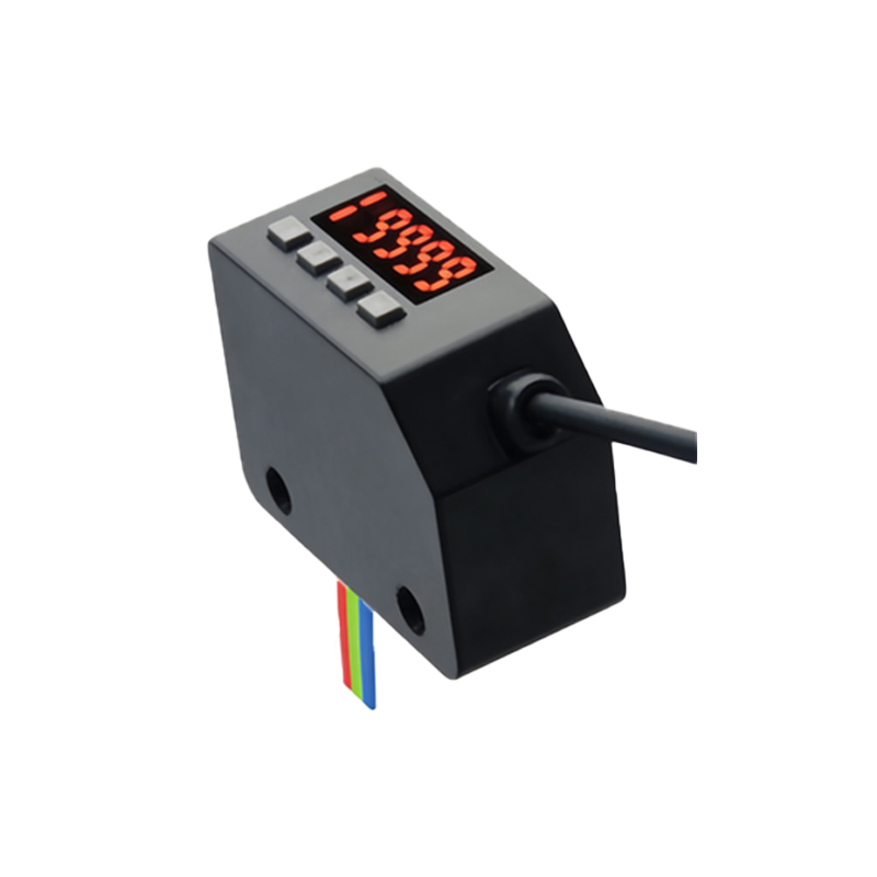
Photoelectric sensors typically offer three output configurations: NPN (sinking), PNP (sourcing), and AC/DC types. For DC-powered sensors, NPN outputs switch the load to ground when activated, while PNP outputs switch to the positive supply. Most SSRs require a DC control voltage (typically 3-32 VDC) to trigger the internal LED. Therefore, you must match the sensor’s output type with the SSR’s input requirements. For example, a PNP sensor can directly drive an SSR with a positive trigger, whereas an NPN sensor may need a pull-up resistor or an interface relay.
Selecting the Appropriate Solid State Relay
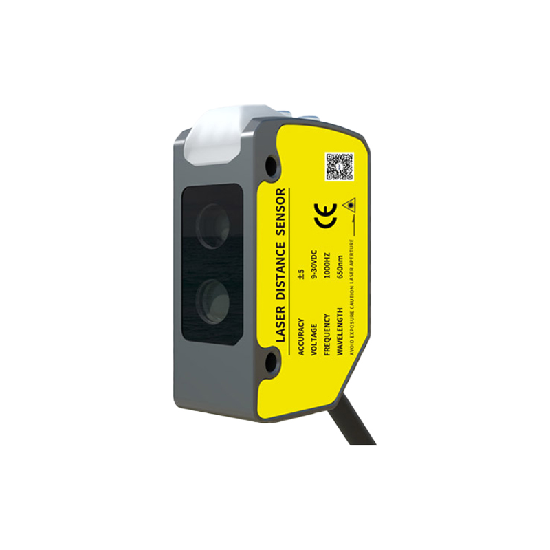
Choose an SSR based on the load voltage and current (AC or DC), as well as the control voltage range. For photoelectric sensor integration, a DC-controlled SSR with a low input current (5-20 mA) is recommended to avoid overloading the sensor’s output. Also, consider the SSR’s isolation voltage and switching speed. For high-speed applications, look for SSRs with zero-crossing switching or random-turn-on options to minimize electrical noise.
Wiring Diagram and Connection Steps
Start by disconnecting all power sources. For a typical PNP sensor connection, connect the sensor’s brown wire to the positive supply (+24 VDC), the blue wire to ground (0 V), and the black output wire to the SSR’s positive control terminal. Then, connect the SSR’s negative control terminal to ground. For NPN sensors, connect the output (black wire) to the SSR’s negative control terminal, and the positive control terminal to the power supply. Always verify polarity using a multimeter before powering up. Use shielded cables for long distances to prevent noise interference.
Adding Protection Components
To enhance reliability, install a freewheeling diode (e.g., 1N4007) across the SSR’s control input if the sensor provides an inductive load. Additionally, place a varistor or RC snubber across the SSR’s output to suppress voltage spikes from the load. A fuse in series with the load side is mandatory for overcurrent protection. For sensors with open-collector outputs, a pull-up resistor (1k to 10k ohms) may be required to ensure a clean logic high signal.
Testing and Troubleshooting Common Issues
After wiring, apply power and check the sensor’s indicator light. If the SSR does not switch, measure the control voltage at the SSR terminals: it should be within the specified range. Common issues include incorrect polarity, insufficient drive current (e.g., sensor output current below SSR’s minimum trigger current), or ground loops. Use an oscilloscope to inspect signal integrity if erratic switching occurs. For high-frequency applications, ensure the sensor’s response time matches the SSR’s turn-on/turn-off delay.
Best Practices for Industrial Environments
Mount the SSR on a heatsink if the load current exceeds 2 amps, as SSRs generate heat during operation. Keep sensor cables separate from high-power lines to reduce electromagnetic interference. Label all connections clearly and use terminal blocks for easy maintenance. Finally, review the datasheets of both components to confirm compatibility, especially regarding temperature ranges and humidity ratings.