Understanding the Photoelectric Sensor Interface
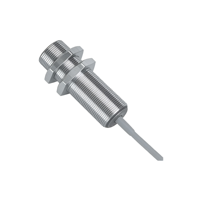
Photoelectric sensors are fundamental components in industrial automation, used for object detection, distance measurement, and presence sensing. These sensors typically output a digital or analog signal based on light reflection or interruption. The most common output types are NPN (sinking) and PNP (sourcing), with three-wire configurations (V+, GND, and signal). When connecting to an IO module, engineers must first identify the sensor’s output type to match the module’s input channel. For example, a PNP sensor provides a positive voltage when activated, while an NPN sensor sinks the signal to ground. This distinction is critical to avoid wiring errors that could damage the IO module or sensor. Always consult the sensor datasheet for voltage ratings, typically 10-30V DC, and ensure the IO module’s power supply matches.
Wiring the Sensor to the IO Module
Proper wiring is essential for reliable operation. Start by connecting the brown wire (V+) to the positive terminal of the power supply, typically 24V DC. The blue wire (GND) connects to the common ground. The black wire (signal) goes to the designated input channel on the IO module. For PNP sensors, the signal wire sends a high signal to the module when the sensor is triggered. For NPN sensors, the signal wire pulls the input to ground. Use shielded cables for long runs to minimize electromagnetic interference. Terminate the shield at the module end only. Verify the IO module’s input specifications—some modules accept both PNP and NPN via configurable inputs. If using a sinking module, ensure the sensor’s output is compatible.
Configuring the IO Module Input Channel
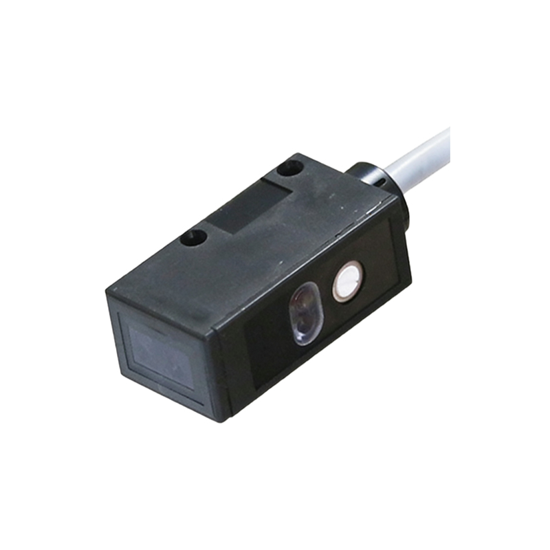
After wiring, configure the IO module’s input channel in the PLC or controller software. Most modern IO modules allow selection between sinking and sourcing modes via DIP switches or software. Set the input filter time to match the sensor’s response speed—typically 1-10 ms for photoelectric sensors. Adjust the debounce setting if the sensor exhibits chatter due to vibration or reflective surfaces. For analog photoelectric sensors, configure the module’s analog input range (e.g., 0-10V or 4-20mA) and scaling parameters. In the PLC program, assign the input channel to a logic variable. For example, a digital sensor’s normally-open output will be HIGH when an object is detected. Test the configuration by triggering the sensor and monitoring the input status in the programming environment.
Troubleshooting Common Connection Issues
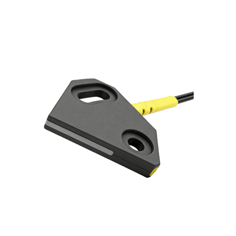
Common issues include no signal, false triggers, or intermittent faults. Start by checking the power supply voltage at the sensor’s V+ and GND terminals with a multimeter—expect 24V DC ±10%. If the signal is missing, verify the sensor’s indicator LED; it should illuminate when detecting an object. For IO modules, check the input status LED for a lit condition. False triggers often stem from incorrect PNP/NPN wiring—ensure the module’s input type matches the sensor. Intermittent faults may be due to loose connections or noise. Use a shielded cable and separate power cables from sensor cables. If the sensor’s output is analog, verify the signal integrity with a scope. In severe cases, install a signal isolator between the sensor and IO module. Document all wiring and configuration steps for future maintenance.
Best Practices for Industrial Deployment
For long-term reliability, follow these best practices. Use terminal blocks or pre-wired connectors for easy replacement. Label all cables with the sensor type, IO channel, and function. Implement surge protection on power lines to prevent damage from transients. In dusty or wet environments, select sensors with IP67 or higher ratings. Test the entire system under all operating conditions, including edge cases like low light or reflective surfaces. Regularly inspect connections for corrosion or wear. For high-speed applications, use sensors with fast response times and IO modules with low latency. Maintain a spare sensor for critical points to minimize downtime. Finally, train maintenance staff on the correct wiring and diagnostic procedures.