Understanding the Basics of 4-Core Photoelectric Sensors
As an electrical engineer working in industrial automation, you often encounter photoelectric sensors with 4-core cables. These sensors typically use a standard color-coding scheme: brown for power supply positive (usually 10-30V DC), blue for power supply negative (0V or ground), black for normally open (NO) output, and white for normally closed (NC) output. Some sensors may vary, so always consult the manufacturer's datasheet. The 4-core configuration provides flexibility for both sinking (NPN) and sourcing (PNP) wiring in control systems.
Identifying Wire Functions and Color Codes
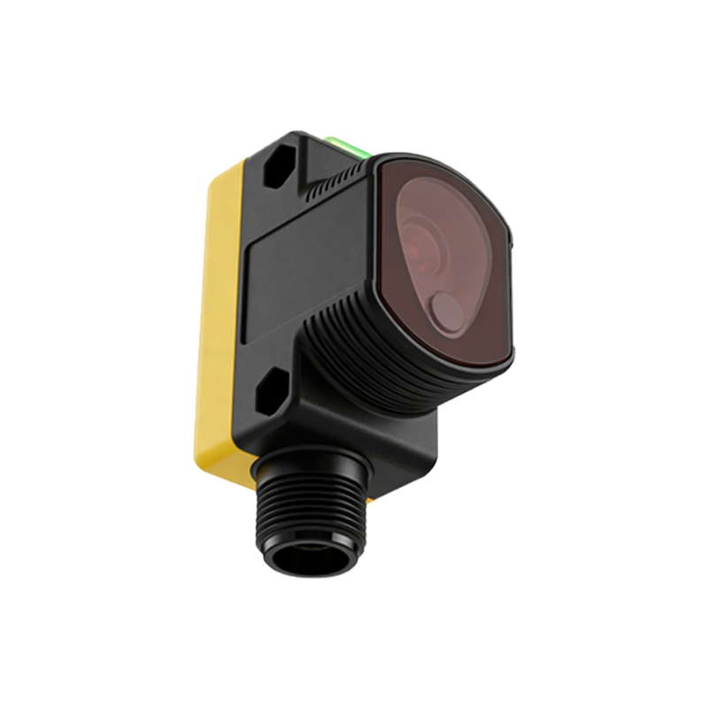
Before starting, verify the wire colors with a multimeter. Brown wire connects to the positive terminal of your power supply. Blue wire goes to the negative terminal or ground. Black wire is the primary output, typically active when the sensor detects an object. White wire serves as the complementary output, active when no object is detected. For PNP sensors, the output wires switch positive voltage; for NPN sensors, they switch ground. Misidentification can cause short circuits or damage to the PLC input module.
Wiring the Power Supply Connections
Connect the brown wire to the +24V DC terminal of your power supply. Ensure the power supply is rated for the sensor's voltage range, typically 10-30V DC. Connect the blue wire to the 0V or ground terminal. Use appropriate fuses or circuit breakers to protect against overcurrent. For longer cable runs, consider voltage drop and use thicker gauge wires if necessary. Always power off the system before making connections to avoid electric shock or damage.
Connecting the Output Wires to a PLC or Controller
For a standard discrete input module, connect the black wire to the input terminal for normally open operation. This means the input will be high when the sensor detects an object. Connect the white wire to another input terminal for normally closed operation if needed. In a PNP configuration, the output wires deliver positive voltage to the input module. In an NPN configuration, they sink to ground. Ensure your PLC input module is configured for the same type (sourcing or sinking) as your sensor.
Testing and Troubleshooting the Wiring
After wiring, apply power and test the sensor. Use a multimeter to measure voltage between brown and blue: it should be around 24V DC. Then, check the black wire voltage relative to blue: it should be near 0V when no object is present (NPN) or 24V (PNP), and toggle when an object is detected. If the output behaves incorrectly, check for loose connections, reversed polarity, or mismatched sensor and PLC types. Common issues include wire breakage in cable strains or incorrect sensor alignment.
Best Practices for Industrial Installations
Use shielded cables for long runs or in noisy environments to prevent electromagnetic interference. Connect the shield drain wire to ground at one end only. Label all wires clearly with heat-shrink markers. Secure cables with cable ties to avoid mechanical stress at connection points. Follow IP rating guidelines for the sensor's housing to ensure dust and moisture protection. Regularly inspect wiring for wear, especially in vibrating machinery.