Introduction to Photoelectric Sensor Reflection Testing
Photoelectric sensors are essential components in modern industrial automation, enabling non-contact detection of objects in diverse environments. Reflection testing, a critical evaluation method, ensures these sensors operate reliably by assessing their ability to detect reflective surfaces accurately. This guide covers the principles, setup, and troubleshooting for photoelectric sensor reflection testing, tailored for electrical engineers seeking to optimize performance in real-world applications.
Principles of Reflection Mode Operation
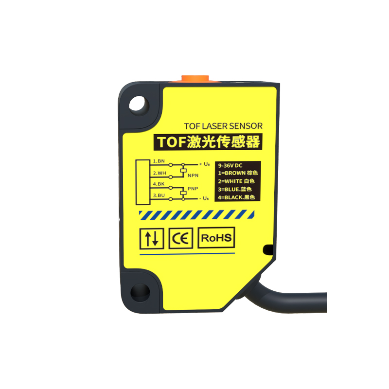
In reflection mode, a photoelectric sensor emits a light beam (typically infrared or visible red) and detects the reflected light from a target or a retroreflector. The key principle is that the sensor’s receiver must differentiate between the emitted signal and ambient light interference. Engineers must understand the relationship between target reflectivity, distance, and sensor sensitivity. For example, high-gloss surfaces like metals or mirrors require careful calibration to avoid false triggering, while matte surfaces demand higher gain settings.
Setting Up a Reflection Test Environment
To conduct a reliable reflection test, follow these steps:
1. Select a test surface representative of the target material (e.g., white paper, aluminum foil, or retroreflective tape).
2. Mount the sensor at a standard distance (e.g., 1 meter) perpendicular to the surface.
3. Control ambient lighting to minimize interference; use a dark enclosure if necessary.
4. Connect the sensor to a power supply and output monitoring device (oscilloscope or PLC input).
5. Adjust the sensor’s sensitivity potentiometer or digital settings to achieve a stable output.
Document all parameters, including wavelength, modulation frequency, and background suppression settings.
Common Test Parameters and Measurement Metrics
Key parameters to evaluate include:
- Detection range: The maximum distance at which the sensor reliably detects the target.
- Excess gain: The ratio of received light to the threshold level, indicating margin against contamination.
- Response time: The delay between object presence and output signal change.
- Hysteresis: The difference in detection distance between approaching and receding objects.
Use a calibrated light meter or sensor analyzer to record these metrics. For example, a typical retroreflective sensor may achieve 5% hysteresis and 1 ms response time under ideal conditions.
Troubleshooting Common Reflection Testing Issues
Engineers often encounter problems such as:
- False detections: Caused by shiny backgrounds or adjacent reflective objects. Solution: Use polarized retroreflective sensors or adjust the sensing angle.
- Reduced range: Due to lens contamination or target misalignment. Solution: Clean optics with lint-free cloth and realign using a laser pointer.
- Ambient light noise: Especially from fluorescent or LED sources. Solution: Employ modulated sensors with bandpass filters.
- Dead zones: Where the sensor fails to detect due to geometric constraints. Solution: Reconfigure the mounting position or use a diffuse sensor variant.
Always verify results with multiple test trials to ensure consistency.
Advanced Techniques for Challenging Applications
For non-standard surfaces, such as transparent or highly specular materials, engineers may employ:
- Background suppression: Using triangulation or time-of-flight sensors to ignore objects beyond a set threshold.
- Dynamic gain control: Automatic adjustment based on real-time reflection intensity.
- Multi-sensor arrays: Combining multiple emitter-receiver pairs for redundancy.
For example, in a glass bottle inspection line, a photoelectric sensor with a narrow beam angle and high-frequency modulation can distinguish between glass and air gaps.
Calibration and Maintenance Best Practices
Regular calibration ensures long-term reliability:
- Perform baseline tests monthly using a standard reflector.
- Document drift patterns and replace components if excess gain drops below 1.5x.
- Use a test jig with known distances (e.g., 0.5m, 1m, 2m) to verify linearity.
- Train maintenance staff to recognize sensor output anomalies (e.g., flickering signals).
Adhering to these practices reduces downtime and improves system accuracy.
Conclusion: Optimizing Sensor Performance Through Rigorous Testing
Reflection testing is not a one-time task but an ongoing process integral to industrial automation. By mastering the principles, setup, and troubleshooting methods outlined here, electrical engineers can ensure photoelectric sensors achieve peak performance in demanding environments. Always prioritize safety and data-driven decision-making to enhance operational efficiency.