Laser sensors represent a sophisticated category of measurement devices that rely on the precise emission and detection of light. At their core, these systems are not merely optical assemblies but intricate electronic circuits that enable their high accuracy and reliability. Understanding the circuit design is fundamental to grasping how laser sensors function across diverse applications, from industrial automation to consumer electronics.
The primary electronic circuit within a typical laser sensor can be broadly divided into several key subsystems: the laser driver circuit, the photodetector interface, signal conditioning and processing circuitry, and the output stage. Each plays a critical role in the sensor's operation.
The journey begins with the laser driver circuit. This is the power source and control unit for the laser diode. Its primary function is to provide a stable, constant current to the laser diode, as even minor fluctuations can cause significant variations in optical output power and wavelength, leading to measurement errors. A high-quality driver circuit includes current regulation, often using a dedicated laser diode driver IC or a precision operational amplifier in a constant-current configuration. It also incorporates safety features like soft-start circuits to prevent current surges that could damage the delicate diode and temperature compensation elements, as laser diode characteristics are highly temperature-sensitive. For pulsed operation, as used in time-of-flight distance sensors, the driver must generate extremely fast and precise current pulses.
The emitted laser light interacts with the target and is reflected or scattered back. This returning light, often vastly attenuated, is captured by a photodetector, typically a photodiode or an avalanche photodiode (APD) for very weak signals. The circuit interfacing with this detector is crucial. A photodiode can be operated in either photovoltaic (zero-bias) or photoconductive (reverse-biased) mode. The most common circuit is a transimpedance amplifier (TIA). This configuration converts the photodiode's tiny output current (which is proportional to the incident light intensity) into a usable voltage signal. The design of the TIA is paramount; it requires a low-noise, high-speed operational amplifier with carefully selected feedback resistors and capacitors to achieve the necessary bandwidth and signal-to-noise ratio without oscillation. For APDs, an additional high-voltage, highly stable bias supply circuit is required.
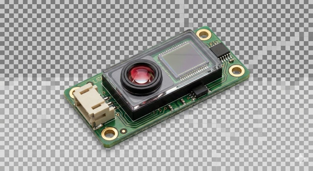
The raw voltage signal from the TIA is usually weak and noisy. This is where the signal conditioning and processing circuitry takes over. This stage often involves filtering to remove unwanted electrical noise and ambient light interference (often achieved with band-pass filters tuned to the laser's modulation frequency). Amplification follows, using precision amplifiers to boost the signal to a level suitable for further processing. In modulated or pulsed systems, this stage may include demodulation circuits or high-speed comparators to precisely time the arrival of the laser pulse.
The processed analog signal is then fed into the processing core. In modern digital laser sensors, this involves an analog-to-digital converter (ADC) and a microcontroller (MCU) or digital signal processor (DSP). The MCU executes algorithms for tasks like distance calculation (using phase-shift or time-of-flight principles), background light cancellation, and data averaging. It also manages communication protocols and system calibration. The circuit design here focuses on clean power supply decoupling, precise clock signals, and proper layout to minimize digital noise affecting the sensitive analog front-end.
Finally, the output stage delivers the sensor's reading to the outside world. This can be a simple digital output (PNP/NPN transistor), an analog voltage or current output (0-10V, 4-20mA), or a serial communication interface like RS-485, IO-Link, or USB. Each output type requires specific supporting circuitry, such as line drivers, isolation circuits, or robust transistor switches capable of driving industrial loads.
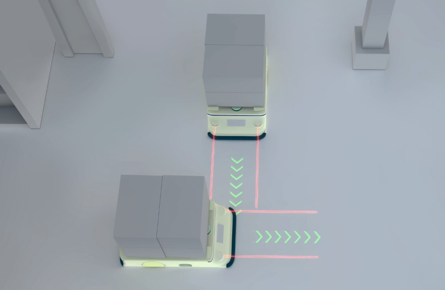
Beyond these core blocks, auxiliary circuits are vital for robust operation. A stable, low-noise power supply regulation network is essential, often using linear regulators for noise-sensitive analog sections and switching regulators for digital parts with proper filtering. Protection circuits against overvoltage, reverse polarity, and electromagnetic interference (EMI) are standard in industrial-grade sensors. Furthermore, many sensors include calibration and temperature compensation circuits, using temperature sensors and lookup tables within the MCU to adjust readings based on ambient conditions.
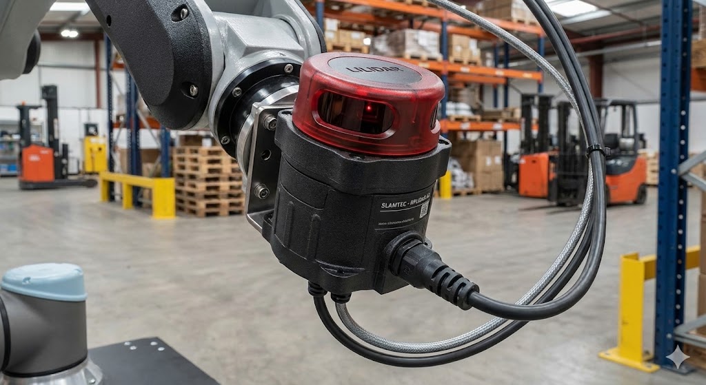
In summary, the circuit design of a laser sensor is a meticulous exercise in analog and digital electronics, blending high-speed signal integrity with precision measurement techniques. From the disciplined current control of the laser driver to the sensitive amplification of the photodetector signal and the intelligent processing in the digital domain, each circuit block must be optimized to work in harmony. This electronic foundation is what transforms a beam of coherent light into a reliable, accurate, and versatile sensing tool, capable of performing in the demanding environments of modern technology.