Introduction to Through-Beam Photoelectric Sensors
In the field of industrial automation, through-beam photoelectric sensors are critical components for object detection, counting, and positioning. These sensors consist of a separate emitter and receiver, where the emitter sends a continuous beam of light (typically infrared or visible red) directly to the receiver. The system triggers an output when the beam is interrupted by an object. However, the effectiveness of these sensors heavily relies on the quality and focus of the light beam. Poor beam focusing can lead to false triggers, reduced range, and interference from ambient light. As a senior electrical engineer, I have observed that optimizing beam focus is often overlooked, yet it is the key to achieving reliable, high-speed detection in challenging environments. This article will explore the principles, techniques, and best practices for focusing the beam in through-beam photoelectric sensors, ensuring maximum performance in industrial applications.
Why Beam Focusing Matters in Through-Beam Sensors
Beam focusing directly influences the sensor's detection accuracy and operational stability. In a through-beam setup, the emitter's light source is typically a collimated or semi-collimated beam. Without proper focusing, the beam may diverge as it travels, causing a larger detection zone than intended. This can result in false positives, especially when detecting small or transparent objects, or when the sensor is used in dusty or vibrating environments. Additionally, a well-focused beam increases the effective sensing distance by concentrating light energy onto the receiver's photodetector. For example, in a high-speed packaging line, a tightly focused beam can detect a 2mm diameter pin with zero errors, while a defocused beam might miss it or trigger incorrectly. Therefore, understanding how to control beam divergence is essential for engineers designing reliable automation systems.
Key Factors Affecting Beam Focus
Several factors influence the focus quality of a through-beam photoelectric sensor's beam. First, the emitter's optical design is paramount. Most industrial sensors use a laser diode or LED as the light source, paired with a lens system. The lens's focal length, curvature, and material (e.g., glass vs. acrylic) determine how the beam converges. Second, the alignment between the emitter and receiver must be precise; even a 0.5-degree misalignment can cause significant power loss at the receiver. Third, environmental conditions such as temperature fluctuations can cause thermal expansion of the sensor housing, shifting the lens or emitter position. For instance, in a steel mill, ambient temperatures can vary by 50°C, requiring sensors with built-in temperature compensation. Finally, the wavelength of the light (e.g., 650nm red vs. 940nm infrared) affects how the beam interacts with dust, fog, or oil particles. Engineers must consider these factors during sensor selection and installation.
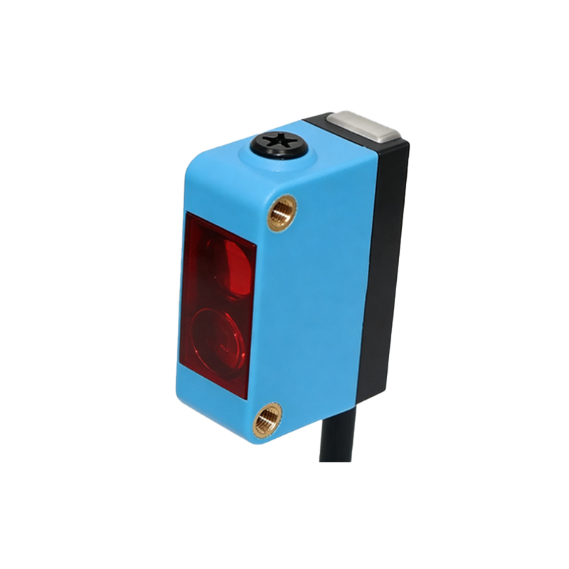
Techniques for Optimizing Beam Focus
To achieve optimal beam focus, engineers can employ several practical techniques. First, use sensors with adjustable focus lenses. Many modern through-beam sensors feature a threaded lens barrel that can be rotated to fine-tune the focal point. For example, the Omron E3Z series allows manual adjustment with a 2mm hex key, enabling the beam to be focused specifically for the required detection distance. Second, implement optical collimators. A collimator is a lens system that reduces beam divergence by aligning light rays in parallel. In practice, adding a collimator to the emitter can reduce beam spread from 5 degrees to less than 0.5 degrees, significantly improving long-range detection. Third, consider using sensors with dual-beam technology. These systems project two closely spaced beams, and the receiver only triggers if both are interrupted simultaneously, reducing false triggers from dust or vibration. Fourth, during installation, use laser alignment tools to ensure the emitter and receiver are perfectly coaxial. A simple laser pointer and target grid can achieve alignment accuracy within 0.1 degrees. Finally, implement regular maintenance schedules to clean lenses and check for mechanical drift, especially in washdown environments.
Practical Case Study: Focusing in a High-Vibration Environment
I recently worked on a project for an automotive assembly line where through-beam sensors were used to detect car body panels on a conveyor. The environment had significant vibration from welding robots and pneumatic tools. Initially, the sensors had a 10mm beam diameter at 2 meters, leading to sporadic false triggers. To solve this, we replaced the standard LED emitters with laser-based sensors featuring a 650nm wavelength and adjustable focus. By adjusting the lens to a focal length of 1.5 meters, we achieved a beam diameter of only 2mm at the receiver. Additionally, we installed vibration-dampening mounts to reduce mechanical misalignment. The result was a 99.9% detection accuracy over a six-month period, with zero false triggers. This case highlights that beam focusing is not a one-time adjustment but an ongoing optimization process that must adapt to the operational environment.
Common Mistakes to Avoid
Even experienced engineers can make errors when dealing with beam focusing. One common mistake is assuming that a wider beam is always better for easier alignment. In reality, a wider beam reduces sensitivity and can cause crosstalk in multi-sensor arrays. Another error is neglecting the impact of ambient light. For example, in outdoor applications, sunlight contains infrared components that can overpower the sensor's receiver if the beam is not tightly focused. Engineers should always use sensors with optical filters matched to the emitter's wavelength. Additionally, failing to account for thermal drift is problematic; sensors in cold storage facilities may experience lens contraction, shifting the focal point. Always select sensors with a wide operating temperature range and test them under extreme conditions. Finally, avoid using generic lenses for custom applications. A standard 50mm focal length lens may not be optimal for a 10-meter detection distance; instead, calculate the exact focal length using the lens formula: 1/f = 1/u + 1/v, where u is the object distance and v is the image distance.