Introduction to Photoelectric Sensors in Die-Cutting Laminating Machines
Photoelectric sensors are critical components in modern die-cutting laminating machines, ensuring precise material alignment, edge detection, and process automation. As an electrical engineer, understanding their working principle is essential for optimizing machine performance, reducing downtime, and maintaining consistent product quality. These sensors convert light signals into electrical outputs, enabling real-time feedback for control systems.
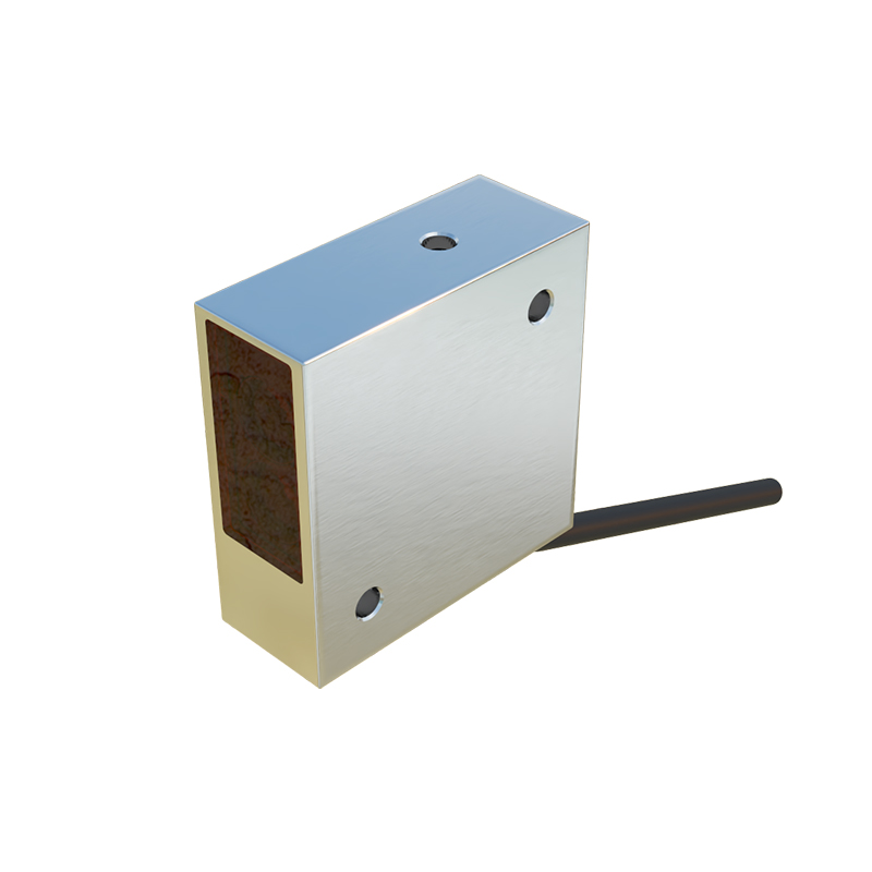
Basic Operating Principle of Photoelectric Sensors
Photoelectric sensors operate by emitting a beam of light, typically from a light-emitting diode (LED), and detecting changes in the received light intensity. When a target material, such as film, paper, or foam, interrupts or reflects the light beam, the sensor’s photodetector generates a corresponding electrical signal. This signal is then processed by the machine’s PLC (Programmable Logic Controller) to trigger actions like stopping the feed, adjusting tension, or initiating a cut. Key parameters include response time, sensing range, and ambient light immunity.
Types of Photoelectric Sensors Used in Die-Cutting Laminating Machines
Three common types are employed: through-beam, retro-reflective, and diffuse reflective sensors. Through-beam sensors consist of separate emitter and receiver units, offering the longest sensing range and highest reliability for edge detection of opaque materials. Retro-reflective sensors use a reflector to bounce the light back, ideal for transparent films. Diffuse reflective sensors detect light reflected directly from the target, suitable for uneven surfaces. Each type must be selected based on material opacity, speed, and environmental conditions like dust or vibration.
Signal Processing and Output Interfaces
The sensor’s output is typically a digital signal (PNP or NPN type) or analog signal for continuous monitoring. In die-cutting laminators, digital outputs are commonly used to indicate the presence or absence of material at a specific point. The signal is conditioned through a threshold comparator circuit, which filters noise and ensures stable detection even with varying material properties. Engineers must calibrate the sensitivity to avoid false triggers from dust or stray light.
Application in Material Alignment and Registration Control
Photoelectric sensors play a key role in maintaining registration accuracy during lamination. For example, a retro-reflective sensor can detect the leading edge of a printed film, triggering the laminating roller to start the bonding process precisely. Through-beam sensors monitor web tension by detecting sagging or breaks. This closed-loop control minimizes waste and ensures that the die-cut patterns align correctly with the laminated layers.
Maintenance and Troubleshooting Tips for Engineers
Common issues include lens contamination, misalignment, and ambient light interference. Regular cleaning with lint-free cloths and alcohol, along with verifying the sensor’s alignment using an alignment tool, can prevent most failures. Engineers should also check the power supply voltage and cable integrity. If false signals occur, adjusting the sensitivity potentiometer or using a baffle to shield from external light sources is recommended. Always refer to the manufacturer’s datasheet for specific electrical ratings and wiring diagrams.