Introduction to Reflective Photoelectric Sensors with Switches
Reflective photoelectric sensors with integrated switches represent a critical component in modern industrial automation. These devices emit a beam of light, typically infrared or visible red, and detect the reflected light from a target object. The integrated switch functionality allows for direct output control, simplifying integration into control systems. Unlike through-beam sensors, reflective types require only one mounting point, reducing installation complexity. In electrical engineering, these sensors are valued for their reliability in detecting objects with varying reflectivity, such as metallic or plastic surfaces, within a defined sensing range.
Operating Principles and Key Components
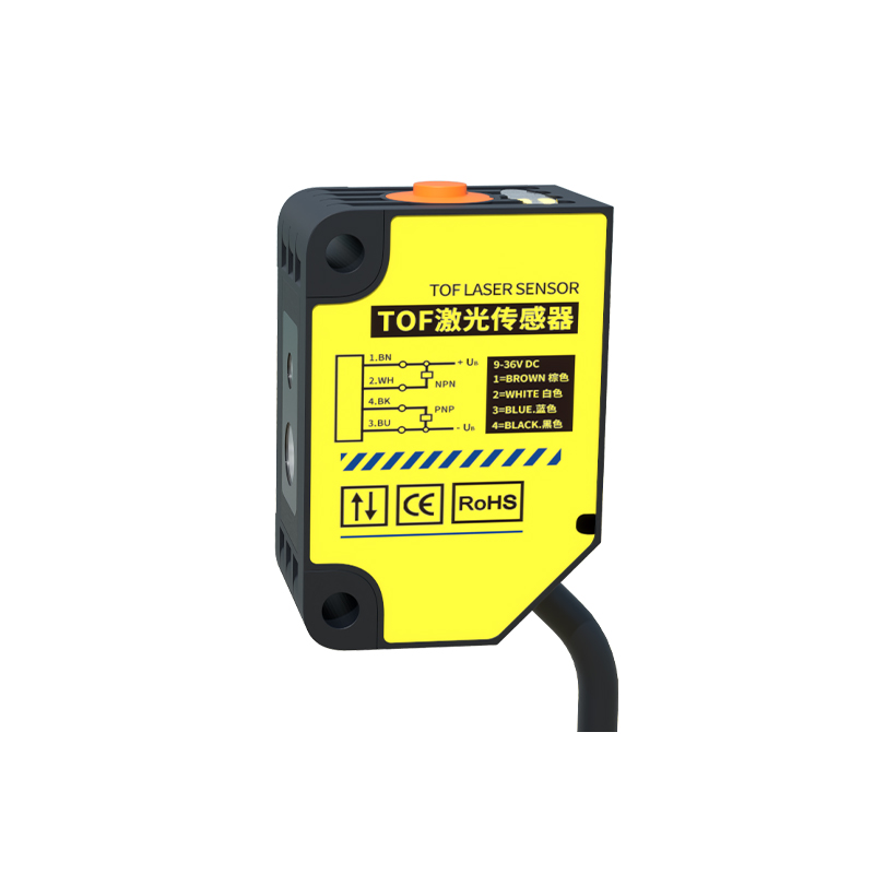
The core operation relies on a light emitter and a photodetector housed in a single unit. The emitter, often an LED, projects a focused beam toward the target. The photodetector captures the reflected signal. The integrated switch circuit processes the received light intensity and triggers a binary output (ON/OFF) based on a preset threshold. Key components include the optical lens for beam shaping, a frequency modulation circuit to reject ambient light interference, and a transistor or relay output. Engineers must consider the sensor’s response time, typically in microseconds, to ensure compatibility with high-speed machinery.
Types of Switching Outputs: NPN, PNP, and Relay
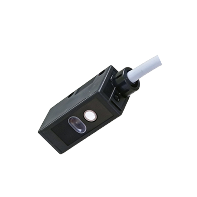
Selecting the correct output type is crucial for system compatibility. NPN (sinking) outputs connect the load to ground when activated, common in Asian and some European systems. PNP (sourcing) outputs provide a positive voltage to the load, prevalent in North American applications. Relay outputs offer galvanic isolation and can handle higher currents, ideal for direct motor or valve control. For example, a PNP output sensor is recommended for PLCs with sourcing inputs. Always verify the sensor’s voltage rating (e.g., 10-30 VDC for transistor types) and maximum switching current to avoid overloading.
Application Scenarios in Industrial Settings
Reflective photoelectric sensors with switches excel in packaging lines, conveyor systems, and material handling. In a bottling plant, a sensor detects the presence of caps on bottles, triggering a reject mechanism via its switch output. In automotive assembly, it verifies the position of parts on a moving belt. For dusty environments, choose sensors with automatic gain control to maintain performance despite lens contamination. Engineers should also consider the target’s color and texture: glossy surfaces reflect more light, allowing longer detection distances, while matte black surfaces may require a sensor with higher sensitivity.
Critical Selection Parameters for Electrical Engineers
When specifying a sensor, evaluate the following: sensing distance (e.g., 10 cm to 2 m), light source type (infrared for invisible operation, visible red for alignment ease), and ambient light immunity. The response time (e.g., 1 ms or faster) must match the machine cycle time. Environmental ratings, such as IP67 for washdown areas, protect against dust and moisture. Additionally, check the electrical interface: some sensors offer IO-Link communication for advanced diagnostics. Mounting options, such as M18 threaded barrels or rectangular housings, affect installation flexibility.
Troubleshooting Common Issues and Maintenance Tips
Common problems include false triggering due to reflective backgrounds or crosstalk from adjacent sensors. To mitigate, adjust the sensitivity potentiometer or use sensors with polarized filters. If the sensor fails to detect, clean the lens with a lint-free cloth and ensure the target is within the specified range. For switch output instability, verify the power supply voltage and check for electromagnetic interference (EMI) from nearby motors. Regular calibration using the teach-in function, available on advanced models, maintains long-term accuracy.