Proximity sensors are critical components in industrial automation, robotics, and safety systems. Their performance and reliability heavily depend on proper mounting and installation. Selecting the correct mounting method ensures accurate detection, minimizes false triggers, and extends the sensor's operational lifespan. This article explores the primary mounting techniques, best practices, and common pitfalls to avoid.
The most fundamental consideration is the sensor's sensing technology—inductive, capacitive, ultrasonic, or photoelectric. Each type has specific mounting requirements related to its operating principle. For instance, inductive sensors, which detect metallic objects, require careful attention to the mounting material and the surrounding metallic environment to prevent interference.
Common Mounting Styles
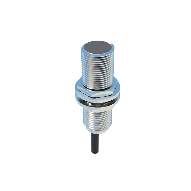
1. Flush Mounting (Embedded Mounting): The sensor's sensing face is installed flush with or recessed behind the mounting surface (e.g., a metal bracket). This style offers excellent mechanical protection for the sensor head from physical damage. It is ideal for applications where the sensor might be subject to impacts, abrasion, or flying debris. However, the effective sensing range (rated operating distance) is reduced compared to non-flush mounting. The surrounding material must be non-metallic for inductive sensors to function correctly in this configuration.
2. Non-Flush Mounting (Non-Embedded): The sensor's sensing face protrudes from the mounting surface. This method provides the full, nominal sensing range as specified by the manufacturer. It is suitable when maximum detection distance is needed and the risk of physical damage to the sensor is low. Non-flush mounting often requires a larger clearance around the sensor head to avoid interference from the mounting structure itself.
3. Threaded Cylinder Mounting: Many cylindrical proximity sensors feature standard threads (e.g., M8, M12, M18, M30). These are mounted using locknuts into drilled and tapped holes in a machine frame or panel. Using the correct size locknut and a sealing washer (for IP-rated sensors) is crucial. Overtightening can damage the sensor housing or threads, while undertightening may lead to loosening from vibration. A spanner wrench should be used on the designated flats of the sensor, not on the housing or electrical connections.
4. Bracket and Slot Mounting: Sensors, especially rectangular or block types, often come with integrated slots or are designed to be used with universal mounting brackets. This allows for adjustable positioning, which is invaluable during machine setup and alignment. Brackets provide flexibility but must be rigid enough to prevent sensor movement during operation. Vibration can cause bracket-mounted sensors to shift, leading to inconsistent detection.
5. Surface Mounting with Adhesives or Tape: In some non-industrial or light-duty applications, double-sided tape or specialized adhesives may be used. This method is generally not recommended for environments with vibration, temperature fluctuations, or where long-term reliability is critical. The bond can degrade over time.
Critical Installation Best Practices
Alignment: Ensure the target approaches the sensor's sensing face perpendicularly for the most consistent and reliable operation. Angular approaches can significantly reduce the effective sensing distance.
Clearance (Side and Face): Maintain adequate clearance between the sensor and any surrounding metal or other sensors. Refer to the manufacturer's datasheet for specific side-clearance and face-clearance requirements. Insufficient clearance can cause mutual interference between sensors or interference from the mounting structure.
Environmental Protection: Choose a sensor with an appropriate Ingress Protection (IP) rating for the environment (e.g., dust, coolant, washdown). Ensure the mounting method preserves this seal. For threaded sensors, properly seat the sealing washer.
Vibration and Shock: In high-vibration environments, use thread-locking compounds (like Loctite) on the sensor threads, employ locking locknuts, or use vibration-damping brackets. Regularly inspect mounts for loosening.
Wiring Strain Relief: Always use a cable gland or proper strain relief clamp to secure the sensor's cable. The connection point at the sensor is vulnerable; stress on the cable can break internal connections or compromise the seal.
Material Compatibility: For flush-mounted inductive sensors, the mounting material surrounding the sensing face must be non-ferrous (e.g., aluminum, plastic, stainless steel). Ferrous material will act as an extension of the sensor's field, causing it to be permanently "on."
Common Mistakes to Avoid
Mounting a sensor without considering the required clearance zones.
Using the sensor body as a mechanical stop for the target.
Overtightening and cracking the sensor housing.
Ignoring temperature specifications, which can affect both the sensor and adhesive mounts.
Failing to account for target material, size, and shape, which influence sensing distance.
In summary,