What Is a Photoelectric Sensor Symbol?
In electrical engineering, a photoelectric sensor symbol is a standardized graphical representation used in schematics and wiring diagrams to identify the device. This symbol typically includes a light source (emitter) and a receiver (detector), often depicted as an arrow indicating the light beam direction. Engineers rely on these symbols to quickly interpret sensor functions without reading lengthy descriptions. The most common symbol follows IEC or ANSI standards, where a rectangle or circle represents the sensor housing, with internal lines showing the emitter and detector components.
Key Components of the Symbol
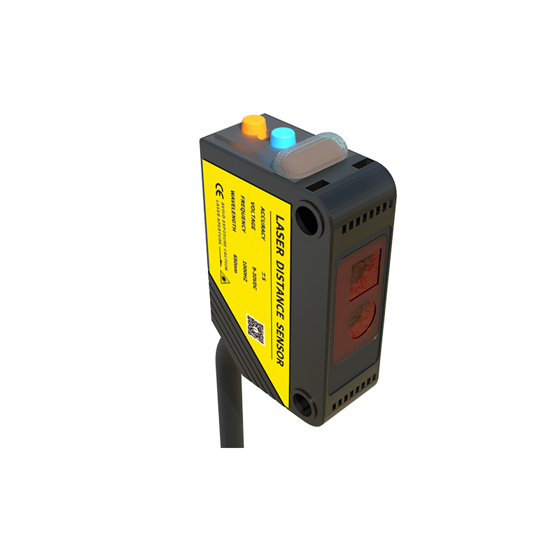
A typical photoelectric sensor symbol consists of two main parts: the emitter (E) and the receiver (R). The emitter is symbolized by a small circle with an arrow pointing outward, representing the light beam emission. The receiver is shown as a circle with a line or a triangle inside, indicating its detection capability. In some variants, a dashed line connects the emitter and receiver to show the sensing path. For through-beam sensors, the two components are separate, while for retro-reflective and diffuse sensors, they are integrated into one unit, reflected in the symbol by a single enclosure with both functions.
Common Symbol Variations for Different Sensor Types
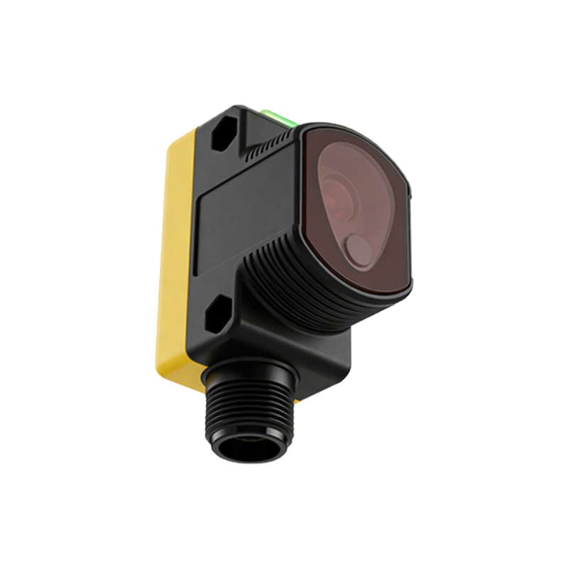
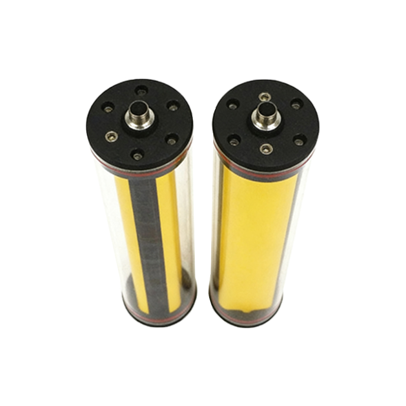
Engineers must recognize symbol variations for different photoelectric sensor types. For through-beam sensors, the symbol shows two separate boxes: one for the emitter and one for the receiver, with a straight arrow between them. Retro-reflective sensors use a single box with an arrow curving back to the same unit, indicating the light beam reflects off a reflector. Diffuse sensors have a single box with a curved arrow pointing toward the target, showing that the object itself reflects the light. These distinctions are critical for accurate circuit design and troubleshooting.
Standardization and Industry Practices
Photoelectric sensor symbols are standardized by organizations like IEC (International Electrotechnical Commission) and ANSI (American National Standards Institute). In IEC 60617, the symbol is defined as a rectangle with an “E” and “R” inside, while ANSI Y32.2 uses a circle with diagonal lines. Many manufacturers also add labels like “PE” (photoelectric) or “PES” (photoelectric switch) near the symbol. Adherence to these standards ensures global understanding, reducing errors in installation and maintenance. Engineers should always reference the latest standard versions for compliance.
Practical Tips for Reading Symbols in Schematics
When reading a schematic with photoelectric sensor symbols, check the symbol’s orientation and nearby labels. For example, an arrow pointing right indicates the light beam direction, while multiple arrows may suggest a multi-functional sensor. Look for pin numbers (e.g., VCC, GND, OUT) near the symbol to understand wiring. Also, note that some symbols include a small “NPN” or “PNP” label, indicating the output type. Practice reviewing common sensor datasheets to match symbols with real-world products, enhancing your ability to design and debug circuits efficiently.