Understanding the Three-Wire Configuration
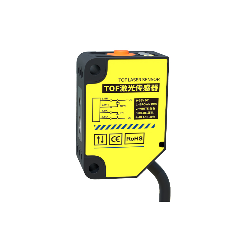
In industrial automation, three-wire photoelectric sensors are standard components for object detection. Unlike two-wire sensors, three-wire models provide separate lines for power and signal, ensuring consistent performance. The three wires are typically color-coded: brown for positive voltage (usually 10-30V DC), blue for negative or ground (0V), and black for the output signal (NPN or PNP type). Understanding this color code is essential before wiring.
Identifying Sensor Output Type: NPN vs. PNP
Before connecting the sensor, determine if it is NPN (sinking) or PNP (sourcing). For NPN sensors, the output (black wire) switches to ground when activated, making it suitable for sinking inputs in PLCs. For PNP sensors, the output switches to the positive supply voltage. Most modern PLCs accept both, but mixing types can cause false triggers or damage. Check the sensor datasheet or label for "NPN" or "PNP" marking.
Step-by-Step Wiring Procedure
1. Power Off: Always disconnect the power supply before wiring to prevent short circuits.
2. Connect Power: Connect the brown wire to the positive terminal (24V DC) and the blue wire to the negative terminal (0V). Use a regulated DC power source within the sensor's rated range.
3. Connect Output: Connect the black wire to the input terminal of your controller (e.g., PLC digital input). For NPN sensors, ensure the controller's input is configured as sinking. For PNP sensors, configure as sourcing.
4. Verify Polarity: Reverse polarity can damage the sensor. Use a multimeter to check voltage between brown and blue before connecting the load.
Common Wiring Mistakes and Troubleshooting
- Mistake: Connecting the output wire to a power source instead of the input terminal. This can burn out the sensor.
- Mistake: Using a load with insufficient current rating. Outputs typically handle up to 100-200 mA; use a relay for higher loads.
- Troubleshooting: If the sensor fails to detect, check the supply voltage at the brown-blue terminals. A reading below 10V may cause unreliable operation. Also, verify the load resistance; some sensors require a minimum load to switch.
Safety and Best Practices
- Use shielded cables in noisy industrial environments to prevent electromagnetic interference. Connect the shield to ground at one end only.
- Avoid running sensor wires parallel to high-power cables. Maintain at least 15 cm separation.
- Use ferrules or tinned ends for stranded wires to ensure secure connections in terminal blocks.
- Test the sensor with a known working load before finalizing installation.