Understanding Photoelectric Sensor Basics
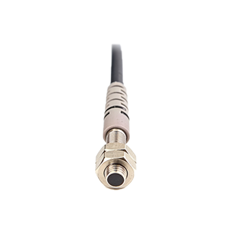
Photoelectric sensors are non-contact devices widely used in automation and manufacturing to detect objects, presence, or distance. They emit a light beam (often infrared or visible) and measure changes in the reflected or interrupted light. Common types include through-beam, retro-reflective, and diffuse-reflective sensors. Each type has distinct wiring requirements depending on output configuration, power supply, and environmental factors. Proper wiring ensures stable performance and minimizes false triggers or damage.
Power Supply and Voltage Considerations
Most industrial photoelectric sensors operate on DC voltage ranging from 10V to 30V DC, though some models support 24V AC/DC. Always verify the sensor's data sheet for voltage ratings. Use a regulated power supply to avoid voltage fluctuations that cause erratic behavior. For long cable runs, consider voltage drop by selecting a thicker gauge wire (e.g., 18 AWG) and keeping the distance under 100 meters. Connect the positive lead to the brown wire and the negative lead to the blue wire, following standard color codes.
Wiring Output Configurations: NPN vs. PNP
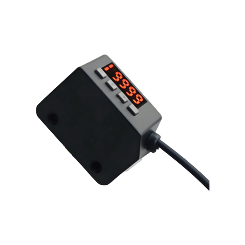
Selecting the correct output type is critical for compatibility with PLCs or controllers. NPN (sinking) sensors switch the load to ground, while PNP (sourcing) sensors switch to positive voltage. For typical PLC inputs, PNP is more common in North America and Europe. The black wire is the output: in NPN, connect it to the load's negative side; in PNP, connect it to the load's positive side. Always check the sensor's marking (e.g., "N.O." for normally open or "N.C." for normally closed) to match the logic of your system.
Shielding and Cable Grounding for Noise Immunity
Industrial environments often contain electromagnetic interference (EMI) from motors, drives, or high-frequency equipment. Use shielded twisted-pair cables for sensor wiring, especially in long runs. Connect the shield drain wire to the sensor's ground terminal or the power supply's ground point, but avoid grounding both ends to prevent ground loops. Keep sensor cables separate from power cables by at least 20 cm to reduce noise. For severe EMI, install ferrite beads near the sensor or controller.
Practical Tips for Installation and Troubleshooting
When mounting sensors, ensure the sensing surface is clean and aligned with the target. For through-beam sensors, maintain precise optical alignment between emitter and receiver. Use waterproof connectors (e.g., M12 or M8) for wet or dusty areas. During troubleshooting, first check the power LED on the sensor. If it's off, verify voltage and wiring polarity. If the output LED is on but the system fails, test with a multimeter at the black wire. Common issues include loose connections, damaged cable insulation, or incorrect load impedance.