Overview of Laser Through-Beam Photoelectric Sensors
Laser through-beam photoelectric sensors are widely used in industrial automation for precise object detection, alignment, and distance measurement. These sensors consist of a separate emitter and receiver, with the laser beam forming a direct line between them. Unlike retro-reflective or diffuse sensors, through-beam sensors offer the highest detection range and immunity to ambient light, making them ideal for harsh environments. Proper wiring is critical to ensure reliable operation, minimize noise interference, and comply with safety standards.
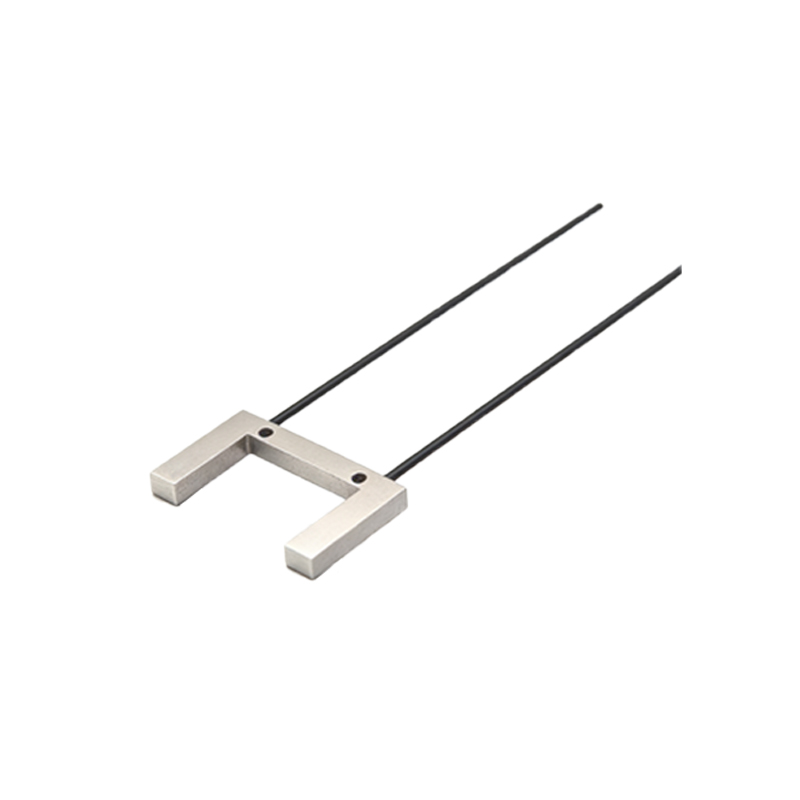
Identifying Sensor Components and Wiring Terminals
Before wiring, examine the sensor housing. Typical terminals include power supply (VCC or +), ground (GND or -), output (NO or NC), and sometimes a test input or alarm output. Laser through-beam sensors often have color-coded wires: brown for VCC (typically 10-30 VDC), blue for GND, black for normally open (NO) output, and white for normally closed (NC) output. Some models feature a built-in amplifier with separate connector pins. Always refer to the manufacturer's datasheet to verify pin assignments, as polarity reversal can damage the sensor.
Step-by-Step Wiring Procedure
1. Disconnect Power: Ensure all power sources are off before starting. Use a multimeter to confirm zero voltage.
2. Connect Power Supply: Connect the brown wire to the positive terminal of a DC power supply (e.g., 24 VDC) and the blue wire to the negative terminal. Use a fused power supply to protect against surges.
3. Wire Output Signals: For a standard NO configuration, connect the black wire to the input of a PLC or relay. If a NC output is required, use the white wire. Ensure the load (e.g., relay coil) is rated for the sensor's maximum switching current (typically 100-200 mA).
4. Shielded Cable Usage: For long cable runs (over 10 meters), use shielded twisted-pair cables. Connect the shield drain wire to the earth ground at the power supply end only, avoiding ground loops.
5. Terminal Block Integration: If using terminal blocks, secure each wire with a screw or spring clamp, verifying no loose connections. Apply heat-shrink tubing or electrical tape for insulation.
Aligning the Emitter and Receiver for Optimal Performance
After wiring, align the emitter and receiver. Mount both units on stable brackets, ensuring their optical axes are coaxial. Use a laser alignment tool or a simple sighting method: power the sensor, adjust the receiver's position until the output indicator lights up steadily. For long distances, use a reflective target temporarily at the receiver end. Check for obstructions like dust or vibration. Secure all mounts after alignment.
Common Wiring Mistakes and Troubleshooting
- Reversed Polarity: Incorrect VCC and GND connections can instantly destroy the sensor. Double-check wire colors.
- Incorrect Output Type: Using NO wiring for a NC application may cause false triggers. Verify the sensor's output logic.
- Cable Length Limits: Excessive cable length (over 100 meters) may cause voltage drop or signal degradation. Use a signal booster or lower resistance cable.
- Noise Interference: If the sensor triggers randomly, check for nearby high-voltage cables or motors. Add ferrite beads or use shielded cables.
- Misalignment: If the output remains off, inspect the laser beam path for misalignment or contamination. Clean lens windows with a lint-free cloth.
Safety Precautions and Best Practices
Laser sensors emit visible or invisible radiation. Class 1 or Class 2 lasers are safe under normal conditions, but avoid direct eye exposure. Use appropriate personal protective equipment. For hazardous environments (e.g., explosive atmospheres), select intrinsically safe sensor models and follow zone-specific wiring regulations. Label all cables clearly for maintenance. Test the system with a simulated object to verify correct switching behavior before full operation.