Understanding the Sensor Types and Their Wiring Basics
Long-distance photoelectric sensors are essential in industrial automation for detecting objects over ranges exceeding several meters, often used in conveyor systems, logistics, and heavy machinery. The wiring process varies depending on the sensor type: through-beam, retro-reflective, or diffuse. For through-beam sensors, the emitter and receiver are separate units; wiring involves connecting the emitter to a power source (typically 10-30V DC) and the receiver to both power and output lines. Retro-reflective sensors integrate emitter and receiver in one housing, requiring a reflector; wiring includes a common power supply and a single output cable. Diffuse sensors emit a beam and detect reflected light from the target, with wiring similar to retro-reflective but no reflector needed. Always check the datasheet for specific voltage and current ratings to avoid damage.
Identifying the Wire Color Codes and Their Functions
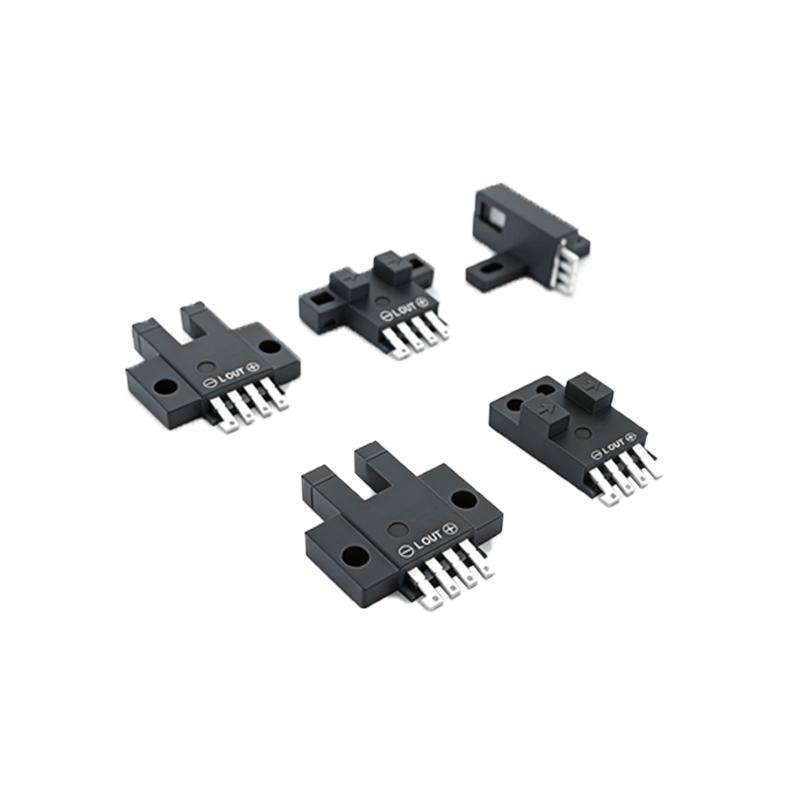
Standard color codes follow the IEC 60947-5-2 standard: brown for positive power (V+), blue for negative power (V- or 0V), black for normally open (NO) output, and white for normally closed (NC) output. Some sensors include a gray wire for alarm or test functions. For long-distance sensors, the output type can be NPN (sinking) or PNP (sourcing). In NPN configuration, the black wire connects to the load and the blue wire to ground; when the sensor detects an object, the output switches to ground. In PNP configuration, the black wire supplies positive voltage to the load. Verify the sensor’s label for PNP or NPN designation before connecting to a PLC or controller, as mismatching can cause malfunction.
Connecting Power Supply and Ensuring Proper Voltage
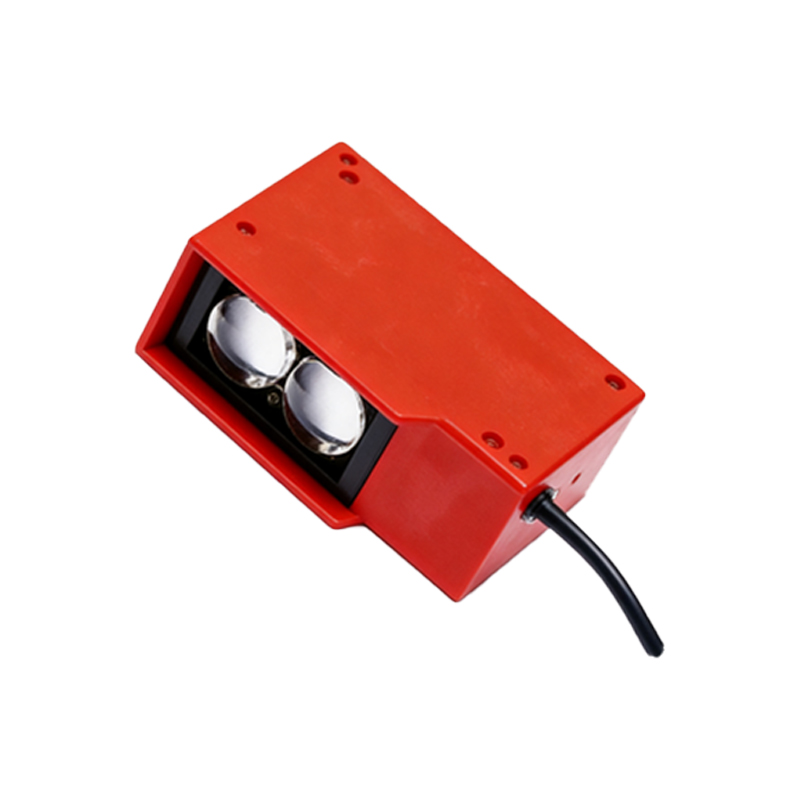
Use a regulated DC power supply with voltage within the sensor’s specified range, typically 12-24V DC. Connect the brown wire to the positive terminal and the blue wire to the negative terminal. For long-distance sensors, consider voltage drop over extended cables; use thicker gauge wires (e.g., 18 AWG) for runs over 20 meters to maintain stable voltage. Include a fuse (e.g., 1A) in the power line to protect against shorts. For sensors with reverse polarity protection, ensure the supply polarity is correct; connecting reverse can damage the sensor. Test the power supply with a multimeter at the sensor end to confirm proper voltage before finalizing connections.
Wiring the Output to a PLC or Controller
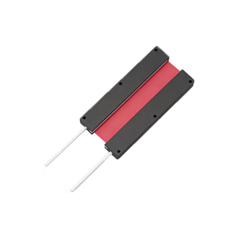
For NPN sensors, connect the black output wire to the PLC’s digital input pin and the blue wire to the common ground. The PLC input should be configured as sinking (NPN) type. For PNP sensors, connect the black output wire to the PLC input and the brown wire to the common positive terminal; configure the PLC input as sourcing (PNP). Use a pull-up or pull-down resistor (e.g., 10kΩ) if the PLC lacks internal resistance, especially in noisy environments. For retro-reflective sensors over long distances, consider using a relay to isolate the output if the PLC input impedance is low. Verify the sensor’s maximum switching current (e.g., 100mA) to avoid overloading the output.
Shielding and Cable Management for Long Distances
Long-distance sensors are susceptible to electromagnetic interference (EMI). Use shielded twisted-pair cables for the output signal, connecting the shield to ground at the PLC end only to prevent ground loops. Keep sensor cables separate from high-power AC lines (e.g., motor cables) by at least 30 cm. For runs over 50 meters, install a signal amplifier or use a fiber optic extender if the sensor uses a 4-20mA analog output. Seal cable joints with waterproof connectors (e.g., M12 connectors) to prevent moisture ingress, which can cause signal degradation over time. Label all wires clearly for maintenance.
Testing and Troubleshooting Common Wiring Issues
After wiring, power up the sensor and use a multimeter to measure voltage between brown and blue wires (should match supply). Test the output: for a NO PNP sensor, measure voltage between black and blue; when an object is detected, voltage should rise to near supply. For NPN, voltage between black and blue should drop to near zero. Common issues include reversed power wires (check for overheating), incorrect output type (swap to PNP or NPN), or loose connections causing intermittent signals. Use a photoelectric sensor tester to verify beam alignment for through-beam types. If the sensor fails to trigger, adjust the sensitivity potentiometer if available, and check for obstructions on the lens.