Understanding the Basics of Photoelectric Sensors and VFDs
Photoelectric sensors are essential components in industrial automation, providing non-contact detection of objects using light. When integrating these sensors with a Variable Frequency Drive (VFD), it is crucial to understand the electrical compatibility and noise immunity. VFDs generate high-frequency electromagnetic interference (EMI) due to pulse-width modulation (PWM) switching, which can disrupt sensor signals. Therefore, proper installation practices are vital to ensure reliable operation and prevent false triggering or sensor damage. Always verify the sensor’s voltage rating (e.g., 24 VDC) and output type (NPN or PNP) before connecting to the VFD control terminals.
Selecting the Correct Sensor and Cable Type
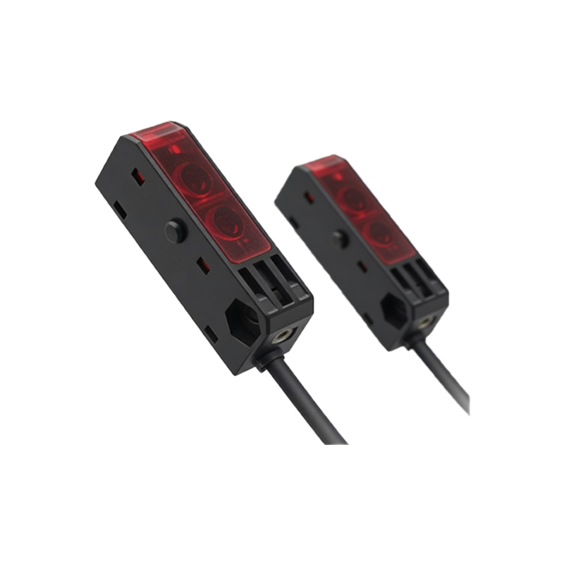
Choose a photoelectric sensor with robust shielding and a high noise immunity rating, preferably with a metal housing for industrial environments. For VFD applications, use twisted-pair shielded cables (e.g., Belden 8760 series) to minimize EMI pickup. The cable length should be as short as possible—ideally under 10 meters—to reduce capacitance effects. If longer runs are unavoidable, install ferrite cores near the sensor and VFD ends. Additionally, ensure the sensor’s switching frequency matches the application speed, as VFDs often control fast-moving machinery like conveyor belts or fans.
Step-by-Step Wiring Procedure for VFD Integration
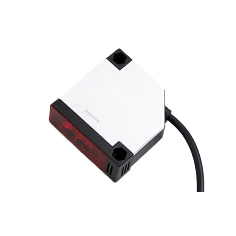
Begin by disconnecting power to both the VFD and the sensor. Locate the VFD’s digital input terminals (e.g., DI1, DI2) designed for external sensor signals. Connect the sensor’s power wires (brown for +24V, blue for 0V) to a separate 24 VDC power supply—never share power with the VFD’s internal supply, as this can cause ground loops. For the signal wire (black for NPN, white for PNP), connect it to the chosen digital input terminal. Then, run the shield wire (drain) to a dedicated ground point on the VFD chassis, avoiding daisy-chaining with motor cables. Finally, use a multimeter to verify continuity and ensure no short circuits before powering up.
Configuring VFD Parameters for Sensor Input
After wiring, access the VFD’s parameter menu (e.g., via keypad or software). Set the digital input function to match the sensor’s intended operation, such as “Run/Stop” (parameter P001) or “Speed Reference Select” (parameter P002). For example, assign DI1 to “External Trip” if the sensor detects a jam. Adjust the input filter time (e.g., 1-5 ms) to debounce the sensor signal and reject high-frequency noise from the VFD carrier frequency. Save the settings and perform a dry test by actuating the sensor manually while monitoring the VFD’s status display.
Testing and Troubleshooting Common Issues
Power on the system and observe the VFD’s response. If the sensor triggers erratically, check for loose connections or excessive cable length. Use an oscilloscope to inspect the signal waveform for spikes or ringing—add a 0.1 µF capacitor across the sensor’s power terminals to suppress noise. If the VFD still registers false signals, reduce the PWM carrier frequency (e.g., from 8 kHz to 4 kHz) in the VFD parameters, though this may increase motor audible noise. Finally, ensure the sensor’s emitter and receiver are properly aligned, and clean the lens to avoid optical interference.
Best Practices for Long-Term Reliability
To extend sensor life in VFD-driven systems, install a surge suppressor on the sensor’s power line and use a separate grounding bar for control wiring. Label all cables clearly for future maintenance. Periodically test the sensor’s response time and compare it with the VFD’s input scan rate (typically 1-10 ms). Also, avoid routing sensor cables parallel to motor power cables for more than 0.5 meters. By following these guidelines, engineers can achieve stable and accurate detection in automated processes, reducing downtime and enhancing system safety.