Introduction to Photoelectric Sensors in Schematics
Photoelectric sensors are essential components in industrial automation, used for detecting objects, distances, and presence without physical contact. In electrical engineering, proper schematic representation ensures clear communication among designers, technicians, and maintenance personnel. This article provides a comprehensive guide on drawing photoelectric sensor symbols according to international standards, such as IEC 60617 and ANSI Y32.2.
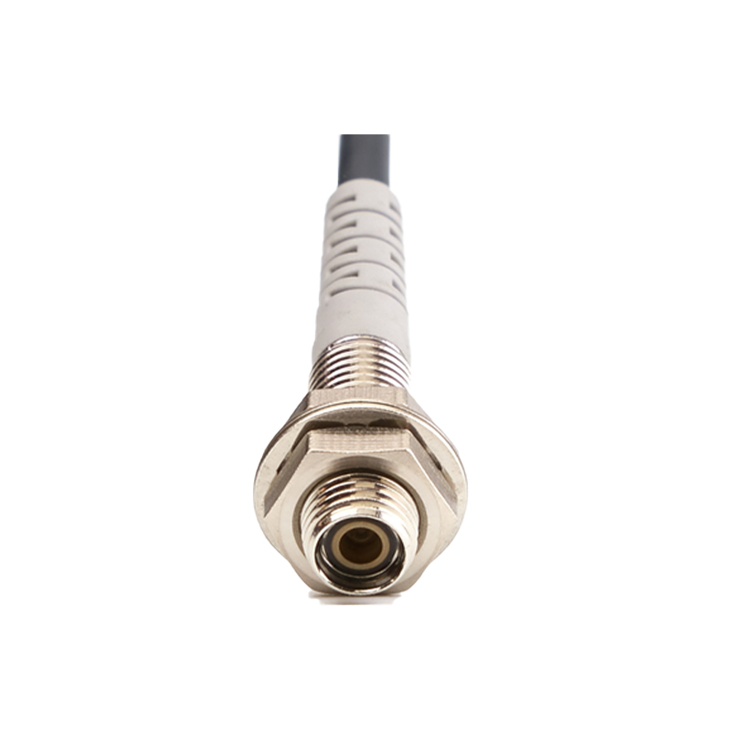
Basic Symbol Components
The standard symbol for a photoelectric sensor consists of a rectangle (representing the sensor housing) with a light source arrow (emitter) and a receiver triangle pointing inward. The emitter is typically drawn as an arrow leaving the rectangle, while the receiver is a triangle with its apex pointing toward the rectangle. Both elements should be placed inside or adjacent to the housing symbol. Use solid lines for active components and dashed lines for optional features like sensitivity adjustments.
Types of Photoelectric Sensors and Their Symbols
There are three main types: through-beam, retro-reflective, and diffuse. For through-beam sensors, draw the emitter and receiver as separate rectangles connected by a dashed light beam line. Retro-reflective symbols include a single rectangle with an arrow and triangle inside, plus a small circle representing the reflector. Diffuse sensors use a similar symbol but without the reflector, indicating the light bounces off the target. Always label each type clearly (e.g., "TB," "RR," "DF") next to the symbol.
Adding Electrical Connections
Each sensor symbol must include power supply lines (typically +V and 0V) and output connections. For DC sensors, draw a positive and negative terminal on the rectangle sides. Output types like NPN (sinking) or PNP (sourcing) should be indicated by a small letter "N" or "P" inside the symbol. For AC sensors, include phase and neutral terminals. Use standard terminal numbering (e.g., 1, 2, 3) per IEC 60947-5-2.
Incorporating Functional Features
Advanced photoelectric sensors may have additional features like teach-in buttons, LED indicators, or timer functions. Represent these as small circles or squares attached to the main rectangle with a connecting line. Label them with abbreviations (e.g., "T" for teach, "LED" for light indicator). For sensors with adjustable sensitivity, draw a diagonal arrow crossing the rectangle to indicate a potentiometer.
Example Schematic Layout
In a typical control circuit, place the photoelectric sensor symbol near the load (e.g., a relay coil or PLC input). Connect the output terminal to the load, and the power terminals to a 24V DC supply. Use a dashed line to show the light beam path if needed. For multi-sensor systems, assign unique reference designations (e.g., "PE1," "PE2") to avoid confusion. Always include a legend explaining all symbols used.
Best Practices for Clarity
Follow consistent drawing conventions: use a 1:1 scale for symbols, maintain 2mm spacing between components, and avoid overlapping lines. Color-code if possible—blue for DC power, red for AC, and green for outputs. Add a title block with project name, date, and revision number. Finally, verify against the latest IEC or ANSI standards to ensure compliance.
Conclusion
Accurate representation of photoelectric sensors in electrical schematics is crucial for system reliability and maintenance. By mastering these symbol drawing techniques, engineers can create clear, standardized diagrams that enhance collaboration and reduce errors. Regularly update your knowledge of evolving standards to stay current in the field.