Understanding the E-Series Photoelectric Sensor Wiring Basics
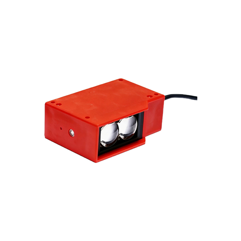
The E-series photoelectric sensors are widely used in industrial automation for object detection, counting, and positioning tasks. Proper wiring is critical to ensure reliable performance and avoid false triggering or damage. The E-series typically comes with three to five wires, depending on the model, including power supply lines (brown for positive, blue for negative), output signal line (black for NPN or PNP), and optional control lines (white for enable or test input). Always confirm the sensor datasheet for your specific model before installation.
Power Supply Connections: Brown and Blue Wires
For the E-series, the brown wire connects to the positive terminal of the DC power supply, typically 10-30 VDC, while the blue wire connects to the negative terminal or ground. Ensure the power supply is stable and within the specified voltage range to prevent sensor malfunction. Use a voltage meter to verify the supply before connecting. For long cable runs, consider using shielded cables to reduce electrical noise, especially in high-interference environments like motor drives or welding areas.
Output Signal Wiring: NPN vs. PNP Configuration
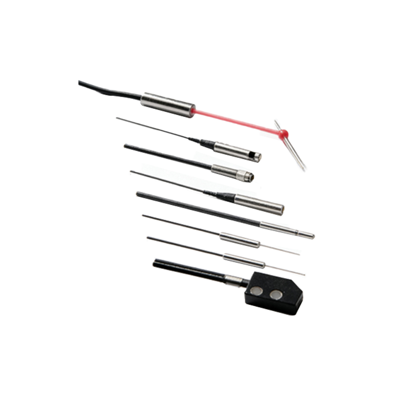
The black wire is the output signal line, which can be configured as either NPN (sinking) or PNP (sourcing) output. In NPN mode, the output transistor switches to ground when the sensor detects an object, so the black wire connects to the load, and the other load terminal goes to the positive supply. In PNP mode, the output switches to the positive supply, so the black wire connects to the load with the other load terminal to ground. For most PLCs, NPN is common in Asian systems, while PNP is preferred in European and American systems. Verify your PLC input type before selecting the mode.
Using the White Wire for Sensor Control Functions
Many E-series sensors include a white wire for additional control, such as enable/disable or test input. When the white wire is connected to the positive supply (for PNP sensors) or ground (for NPN sensors), the sensor is enabled. Leaving it floating or connecting it to the opposite polarity can disable the sensor or activate test mode. Some models use the white wire for light-on/dark-on selection. Refer to the sensor manual to determine the exact function and voltage logic.
Wiring for Noise Immunity and Long Distances
For industrial environments, use twisted-pair cables for power and signal lines to minimize electromagnetic interference. Keep sensor cables away from high-voltage power lines and motor cables. If the cable length exceeds 10 meters, consider using a shielded cable with the shield connected to the ground at the controller side (not both ends) to avoid ground loops. For extreme distances, use a sensor amplifier or remote I/O module.
Common Wiring Mistakes and Troubleshooting
Common errors include reversing the power wires, which can damage the sensor, or miswiring the output to a different voltage than specified. If the sensor does not output a signal, check the power supply voltage first, then verify the output type (NPN vs. PNP) matches the load. Use a multimeter to measure voltage across the output line during detection. If the sensor triggers intermittently, inspect for loose connections or electrical noise. Always disconnect power before changing wiring configurations.
Final Verification and Safety Notes
After completing the wiring, power up the system and test the sensor by passing an object through its detection zone. Confirm the output signal matches the expected logic (normally open or normally closed). Ensure all connections are secure and insulated with heat shrink or electrical tape to prevent short circuits. For safety, always follow lockout/tagout procedures when working on live circuits. Document the wiring configuration for future maintenance.