Understanding Photoelectric Sensor Wiring Basics
Photoelectric sensors are widely used in industrial automation for detecting objects without physical contact. These sensors typically feature three or four wires: power supply (brown for +V, blue for ground), output (black for NPN or PNP), and sometimes a test or shield wire. Shorting wires refers to connecting specific terminals to achieve a desired function, such as disabling a normally open (NO) output or simulating a detection state for testing. Before proceeding, always verify the sensor’s datasheet to avoid damage from incorrect wiring, especially with AC or high-voltage models. Common voltage levels are 10-30 V DC, but some sensors operate at 24 V AC/DC or 100-240 V AC.
Materials and Safety Precautions
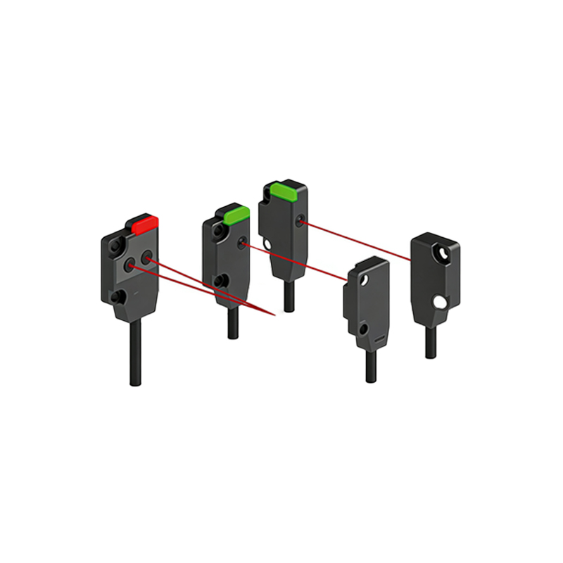
Essential tools include a multimeter, wire strippers, screwdrivers, and heat shrink tubing or electrical tape. Safety is paramount: disconnect power before handling wires to prevent electric shock or short circuits. Use a multimeter to confirm zero voltage on the terminals. Wear insulated gloves if working near live circuits. For high-voltage sensors (e.g., 220 V AC), follow lockout/tagout procedures. Ensure wires are correctly identified by color codes: brown (+V), blue (GND), black (output), and white (test/auxiliary). Some sensors use red or orange for power, so double-check labels.
Step-by-Step Procedure for Shorting Wires
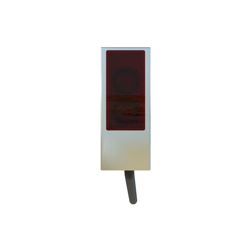
1. Identify Output Type: Determine if the sensor is NPN (sinking) or PNP (sourcing). For NPN, the output wire (black) is connected to ground when active; for PNP, it connects to +V. Shorting the output wire to +V or GND can simulate detection. 2. Power Down: Disconnect the sensor from the power supply. 3. Strip Wires: Expose about 5 mm of conductor on the wires to be shorted (e.g., black output and blue ground for a test). 4. Connect Temporarily: Use a jumper wire or screw terminal to bridge the selected wires. For a normally open (NO) sensor, shorting the output to GND (NPN) or +V (PNP) manually triggers the output as if an object is detected. 5. Insulate: Wrap the connection with electrical tape or heat shrink to prevent accidental shorts. 6. Power On and Test: Reconnect power and use a multimeter to measure voltage across the output and GND. Expect 0 V if shorted to GND (NPN) or +V voltage if shorted to +V (PNP). 7. Document: Label the modified wires for future maintenance.
Common Applications and Troubleshooting
Shorting is often used for diagnostic purposes, such as forcing a sensor to output a signal to test a PLC input or relay. In emergency stop circuits, shorting the normally closed (NC) output to a safe state can bypass a faulty sensor temporarily. However, avoid permanent shorting unless the sensor is designed for it (e.g., some models have a short-circuit protection feature). If the sensor fails to respond, check polarity: reverse voltage can destroy internal electronics. Use a multimeter to verify continuity and voltage levels. For sensors with a test wire (white), shorting it to GND may activate a test mode, but consult the manual.
Important Warnings and Best Practices
Never short power wires (+V and GND) directly, as this causes a short circuit and can damage the power supply or sensor. Always use a current-limiting resistor if required, especially with LED indicators. For outdoor installations, use waterproof connectors to prevent moisture ingress. Follow the manufacturer’s guidelines for wire gauge (typically 22-18 AWG). If the sensor operates on AC voltage, shorting wires may create arcs; use a fuse in series for protection. Finally, restore original wiring after testing to ensure reliable industrial operation.