Introduction to Photoelectric Sensor Output Current
Photoelectric sensors are essential components in industrial automation, used for detecting objects, distances, and positions without physical contact. One critical parameter that engineers must understand is the output current, which directly affects the compatibility with controllers, relays, and other downstream devices. The output current typically ranges from 10 mA to 100 mA, but this varies by sensor type (through-beam, retro-reflective, or diffuse) and output configuration (NPN, PNP, or analog). This article provides a detailed analysis of output current characteristics, including load driving capabilities, voltage drop considerations, and practical selection criteria.
Key Factors Influencing Output Current
The output current of a photoelectric sensor is primarily determined by its internal electronics, such as the output transistor (BJT or MOSFET) and the protection circuitry. For digital sensors (e.g., NPN or PNP), the output current is limited to the transistor's maximum rating, typically 50 mA for standard models, but high-power versions can deliver up to 150 mA. Analog sensors, like those with 4-20 mA output, have a different current range designed for proportional signal transmission. Additionally, the supply voltage influences current capability: lower voltages reduce the available current due to internal voltage drops, while higher voltages allow for higher current but may increase heat dissipation. Engineers must also consider the load impedance, as excessive load resistance can cause voltage sag and reduce effective current.
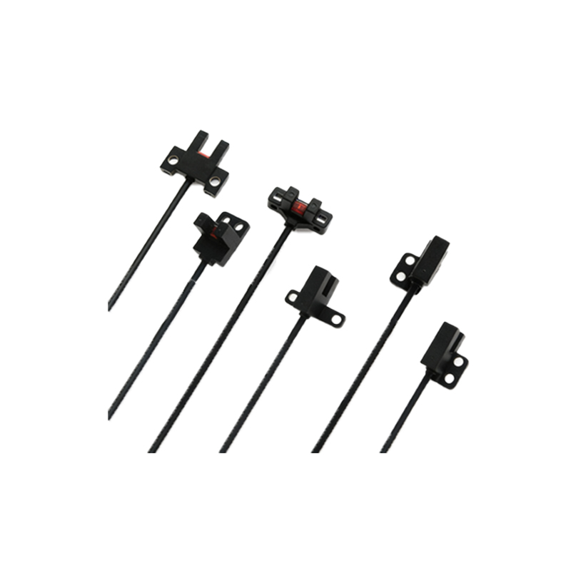
Typical Output Current Values by Sensor Type
- Through-beam sensors: These have separate emitter and receiver units. The receiver output current is usually 20-50 mA for digital types. For analog versions, 4-20 mA is common for distance measurement.
- Retro-reflective sensors: Integrated emitter and receiver with a reflector. Output current ranges from 30-100 mA for digital, and 4-20 mA for analog models. The presence of polarization filters may slightly reduce current due to optical losses.
- Diffuse sensors: These detect objects by reflected light. Digital outputs often provide 10-50 mA, while analog outputs follow the 4-20 mA standard. Short-range diffuse sensors may have lower current due to less powerful LEDs.
- Fiber optic sensors: These use external fiber cables. Output current is typically similar to diffuse sensors (10-50 mA digital), but the amplifier unit may have programmable current limits.
Impact of Output Configuration on Current
- NPN (sinking) output: The sensor sinks current to ground when activated. The output current flows from the load into the sensor. Typical current is 20-50 mA, with a maximum of 50-100 mA. Voltage drop across the sensor is about 0.5-1.5 V at rated current.
- PNP (sourcing) output: The sensor sources current to the load when activated. Current flows from the sensor to the load. Similar current range (20-50 mA), but voltage drop is slightly higher due to the sourcing circuit (1-2 V).
- Push-pull output: Combines NPN and PNP for flexibility. Current capacity is often higher, up to 100 mA, with low voltage drop.
- Analog output: For 4-20 mA loops, the sensor adjusts current proportionally to the sensed parameter. Maximum loop current is 20 mA, with a minimum of 4 mA. The sensor must comply with loop powered or externally powered standards.
Practical Considerations for Load Driving
When selecting a photoelectric sensor, engineers must ensure the output current can reliably drive the intended load. For example, a PLC input module typically requires 5-10 mA per channel, but the sensor must provide enough margin to account for cable resistance and noise immunity. Relays or solenoids may require 20-50 mA, which falls within the typical range. However, inductive loads may cause back-EMF, so flyback diodes are recommended. Additionally, the sensor's maximum current rating should not be exceeded, as it can lead to thermal damage. A rule of thumb is to use a sensor with a rated current at least 1.5 times the load requirement to ensure reliability.
Measurement and Testing Techniques
To verify output current, engineers can use a multimeter in series with the load or a current clamp. For digital sensors, measure current with the sensor in the active state (e.g., object present). For analog sensors, vary the sensing condition and observe the current change. It is important to test under real load conditions, as open-circuit tests may show different values due to internal pull-up resistors. Also, check the voltage drop across the sensor at full current to ensure the load receives sufficient voltage. For example, a 24 V supply with a 1.5 V drop leaves 22.5 V for the load, which is acceptable for most devices.
Conclusion and Recommendations
Understanding the output current of photoelectric sensors is crucial for system design. For most industrial applications, a sensor with 50 mA output current is sufficient for digital loads, while 4-20 mA analog sensors are ideal for proportional control. When in doubt, consult the datasheet for maximum and typical current values, and test under worst-case conditions. Always consider de-rating for high ambient temperatures, as heat reduces current capacity. By following these guidelines, engineers can ensure reliable sensor operation and avoid common pitfalls.