Introduction to Photoelectric Sensor Symbols
Photoelectric sensors are critical components in modern automation systems, converting light signals into electrical outputs. Their electronic symbols, standardized by IEC and IEEE, represent the sensor’s components and functionality in circuit diagrams. For electrical engineers, mastering these symbols is essential for accurate design and troubleshooting in industries like manufacturing, logistics, and robotics.
Basic Symbol Structure of Photoelectric Sensors
The fundamental symbol for a photoelectric sensor includes a light source (often depicted as a triangle or arrow emitting light) and a receiver (typically a rectangle or circle with a photodiode or phototransistor indicator). The emitter and receiver may be combined in a single enclosure or separated, depending on the sensor type. The symbol also includes power supply connections (V+ and V-) and an output terminal (NPN or PNP, depending on the circuit configuration).
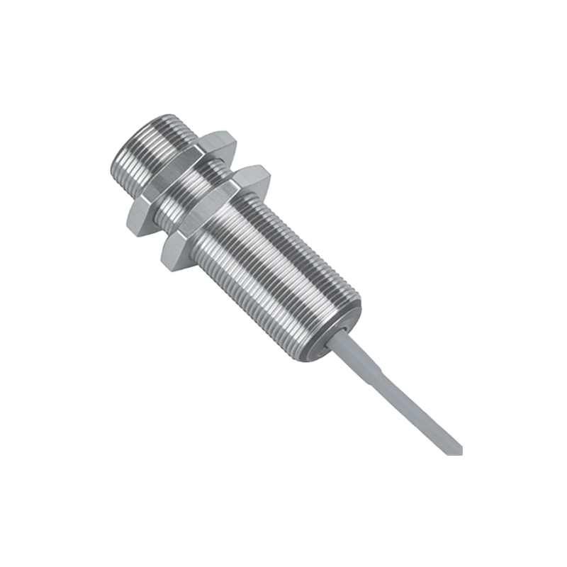
Common Photoelectric Sensor Types and Their Symbols
- Through-beam Sensors: Symbol shows separate emitter and receiver blocks with a direct light path arrow. Output symbol includes a normally open (NO) or normally closed (NC) contact for NPN/PNP logic.
- Retro-reflective Sensors: Symbol includes a single block for the sensor and a separate reflector symbol (a dashed circle with a diagonal line). Light travels from emitter to reflector and back to receiver. The output symbol is similar to through-beam.
- Diffuse-reflective Sensors: Symbol shows emitter and receiver in one block with an arrow pointing to a target (often a dashed line). The output symbol includes an adjustable threshold indicator.
- Fiber Optic Sensors: Symbol uses a fiber optic cable icon (a wavy line) connecting the sensor head to a remote amplifier. The amplifier block includes a light source and receiver with gain adjustment.
Output Configuration Symbols
Photoelectric sensor symbols must clearly indicate the output type. NPN (sinking) outputs are denoted by a downward arrow (sink), while PNP (sourcing) outputs use an upward arrow (source). Additional symbols include:
- Dark-on (DO) vs. Light-on (LO): A small circle or “D”/“L” inside the symbol indicates the logic. For example, a sensor with a “D” inside activates when light is interrupted.
- Analog Output: A sine wave or “A” symbol within the block denotes a variable output (e.g., 0-10V or 4-20mA).
- Digital Output: A square wave or “D” symbol indicates a discrete on/off signal.
IEC vs. IEEE Symbol Differences
IEC 60617 symbols often use simplified blocks with functional labels (e.g., “PE” for photoelectric emitter), while IEEE Std 315 employs more detailed graphical representations. For instance, an IEC symbol for a retro-reflective sensor might just show a rectangle with “R” for reflector, whereas IEEE uses a separate reflector icon. Engineers working across global projects must recognize both standards.
Practical Tips for Reading Symbols on Schematics
- Identify the sensor type first: Look for the arrow direction and reflector icon to determine through-beam, retro-reflective, or diffuse mode.
- Check the output logic: Note any “D” or “L” markings for dark-on/light-on operation.
- Verify power and ground: Ensure V+ and V- connections match the system voltage (e.g., 12-24V DC).
- Consider the load: The symbol often shows a load resistor (RL) connected to the output for NPN/PNP configuration.
Conclusion
Accurate interpretation of photoelectric sensor electronic symbols is vital for designing reliable automation systems. By understanding the basic structure, output configurations, and standard differences, electrical engineers can avoid wiring errors and optimize sensor performance. Always refer to the manufacturer’s datasheet alongside the schematic for complete details.