Introduction to Photoelectric Sensors and Model 555
Photoelectric sensors are critical components in modern industrial automation, offering non-contact detection of objects, distances, and material properties. Among the wide range of models, the 555 series stands out for its reliability and versatility in harsh environments. As an electrical engineer specializing in sensor integration, I will walk through the key technical aspects, installation best practices, and troubleshooting tips for the Model 555. This guide is tailored for professionals seeking to optimize production line efficiency and accuracy.
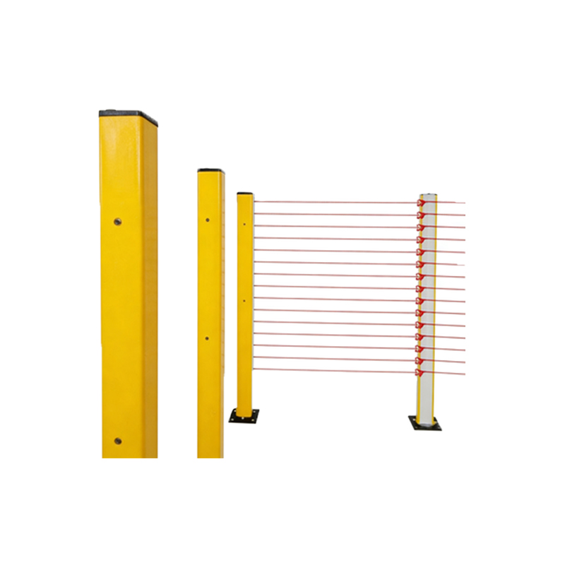
Key Technical Specifications of the 555 Sensor
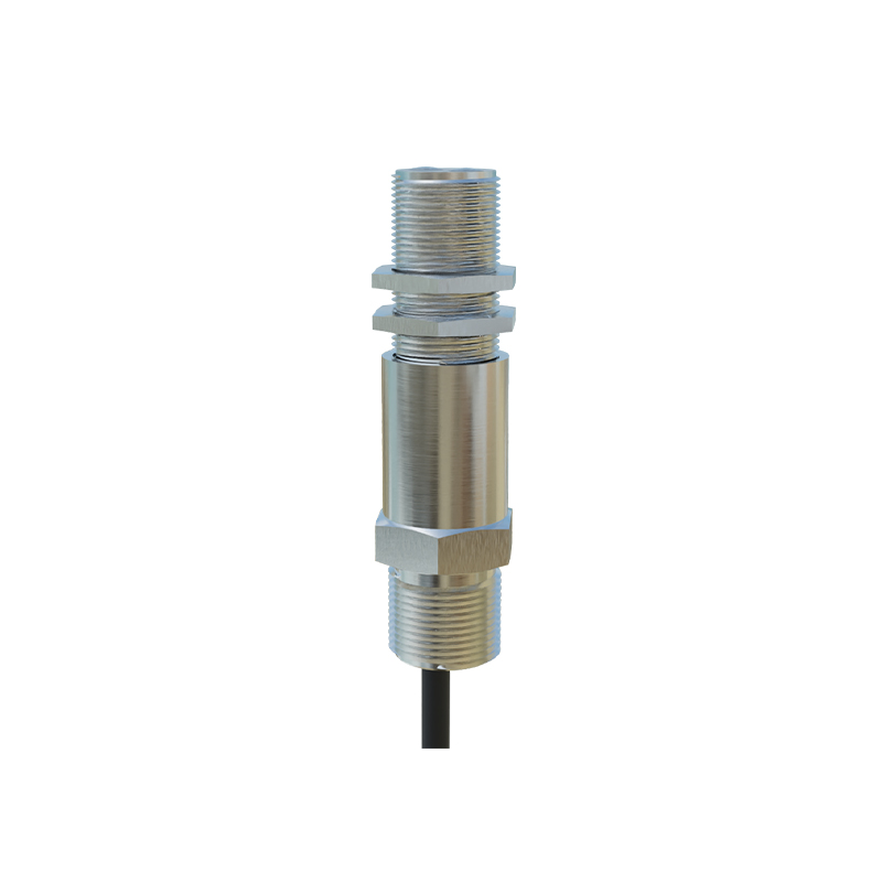
The Model 555 photoelectric sensor typically operates with a supply voltage range of 10-30 VDC, making it compatible with standard industrial power systems. It features a sensing distance of up to 15 meters for through-beam configurations and 5 meters for retro-reflective setups, depending on the target material and ambient conditions. The output is NPN or PNP transistor type, with a response time of less than 1 millisecond, ensuring fast detection for high-speed conveyor lines. The sensor's IP67 rating protects against dust and water ingress, and its operating temperature range of -25°C to 55°C suits most factory floor environments.
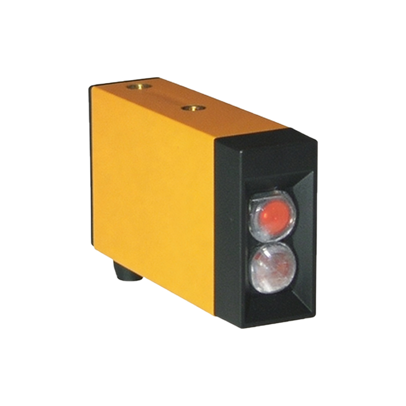
Installation Guidelines for Optimal Performance
Proper mounting is crucial for the 555 sensor to maintain accuracy. For through-beam mode, align the emitter and receiver directly facing each other with no obstructions; use mounting brackets that allow fine adjustment. In retro-reflective mode, position the sensor perpendicular to the reflector and avoid highly reflective backgrounds that could cause false triggers. For diffuse mode, consider the target's color and surface texture—dark objects reduce sensing range by up to 50%. Always shield the sensor cable from electromagnetic interference by using twisted-pair wires and grounding the shield at one end only.
Common Applications in Automation Systems
The 555 sensor excels in packaging, material handling, and assembly line tasks. Examples include detecting product presence on conveyor belts, counting items in high-speed sorters, and verifying component positions in robotic pick-and-place systems. Its adjustable sensitivity via a built-in potentiometer allows fine-tuning for transparent objects, such as glass bottles or plastic films, by compensating for light absorption. In dusty environments, use the sensor with an air purge accessory to keep the lens clean.
Troubleshooting Common Issues
If the 555 sensor fails to detect correctly, first check the alignment and clean the lens with a lint-free cloth. For intermittent false triggers, inspect the wiring for loose connections or proximity to high-voltage lines. Adjust the sensitivity potentiometer gradually while monitoring the output with a multimeter. If the sensor LED indicates a constant static state, verify the supply voltage is within tolerance and the load resistance matches the output specification. For persistent problems, consult the manufacturer's datasheet for specific error codes.
Future Trends and Maintenance Tips
As Industry 4.0 evolves, the 555 series may integrate with IO-Link communication for real-time diagnostics and parameter adjustments. To extend sensor life, schedule periodic inspections every six months, including lens cleaning, cable integrity checks, and calibration verification. Replace the sensor if response time degrades or if physical damage appears on the housing. With proper care, the Model 555 delivers years of reliable service in demanding industrial settings.