Understanding the MR30X Sensor Wiring Basics
The MR30X photoelectric sensor is a versatile device commonly used in industrial automation for object detection. It typically comes with four wires: two for power supply (positive and negative) and two for output (normally open and normally closed). Proper wiring is critical to ensure reliable operation and avoid damage to the sensor or connected equipment. Before starting, always verify the sensor's datasheet for specific voltage and current ratings. The standard wire colors are brown (positive), blue (negative), black (normally open output), and white (normally closed output). Ensure the power supply matches the sensor's specifications, usually 10-30 VDC.
Identifying the Four Wire Functions
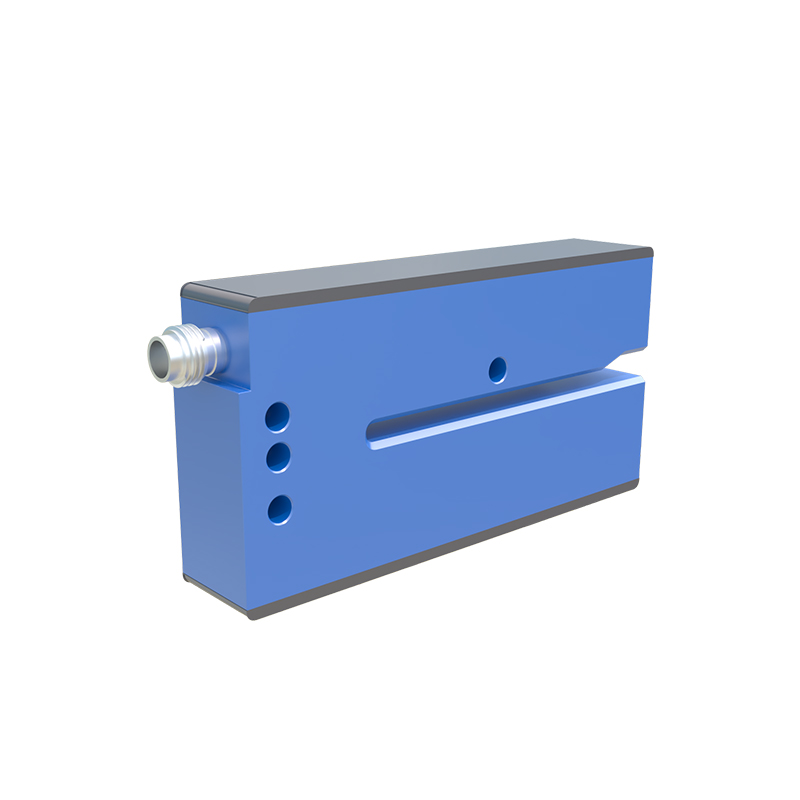
For the MR30X, the four wires serve distinct functions. The brown wire is the power supply positive (V+), typically connected to a 24 VDC source. The blue wire is the power supply negative (V-), connected to the ground of the power supply. The black wire is the normally open (NO) output, which is active when the sensor detects an object. The white wire is the normally closed (NC) output, which is active when no object is detected. In some models, the wire colors may vary, so always refer to the user manual. A multimeter can confirm continuity if colors are unclear.
Preparing the Power Supply Connection
Begin by turning off the power to avoid short circuits. Connect the brown wire to the positive terminal of a regulated DC power supply, ensuring the voltage is within the MR30X's range (e.g., 24 VDC). Connect the blue wire to the negative terminal. Use a fuse in series with the brown wire for overcurrent protection, typically rated at 1A. Verify the connection with a voltmeter to ensure stable voltage. A loose connection can cause intermittent sensor behavior, so tighten screws or use proper crimp connectors. For long cable runs, consider twisted-pair wiring to reduce noise.
Connecting the Output Wires to a PLC or Controller
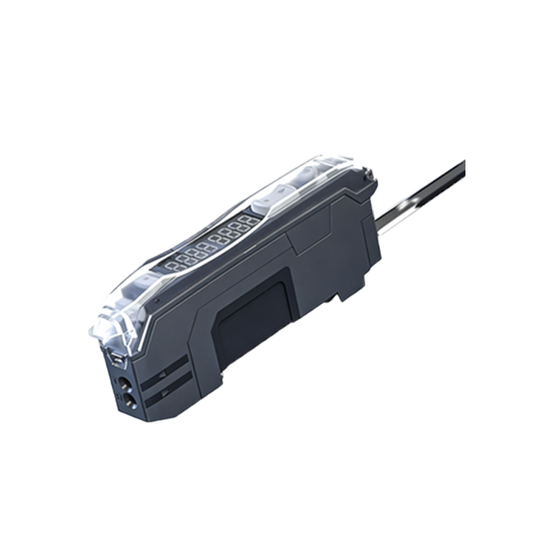
The black and white wires connect to the input module of a PLC, relay, or other controller. For normally open operation, connect the black wire to the PLC's digital input and the white wire to a common ground or leave it unconnected if not used. For normally closed operation, use the white wire instead. Ensure the PLC input is configured for sinking or sourcing based on the sensor type. The MR30X typically has a PNP (sourcing) output, meaning it provides a positive signal when active. Use a resistor if the input impedance is high to avoid false triggers. For example, connect a 10kΩ pull-down resistor between the output wire and ground.
Testing and Troubleshooting the Wiring Setup
After wiring, power on the system and test the sensor by placing an object in its detection range. Use an LED indicator on the sensor (if available) to confirm activation. If the sensor does not respond, check the power supply voltage at the brown and blue wires. A common issue is reversed polarity, which can damage the sensor. Verify the output signal with a multimeter: between black and blue, voltage should be near 24 VDC when an object is detected (NO mode). If the signal is erratic, inspect for loose connections or electromagnetic interference. Shielded cables can help in noisy environments. For persistent faults, consult the MR30X datasheet for diagnostic codes.