Understanding the 24V Infrared Photoelectric Sensor
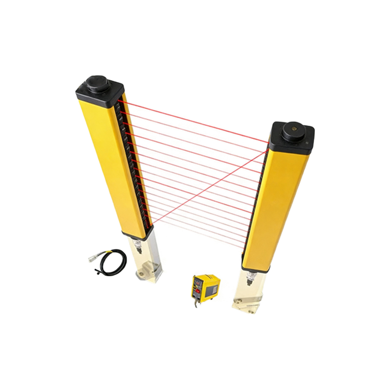
The 24V infrared photoelectric sensor is a critical component in industrial automation, security systems, and safety applications. It consists of a transmitter and receiver pair, using infrared light to detect objects or obstacles. Proper wiring ensures reliable performance and prevents false triggers or equipment damage. This guide focuses on wiring methods for common configurations, including NPN (sinking) and PNP (sourcing) output types.
Identifying Sensor Components and Terminals
Before wiring, inspect the sensor's housing for terminal labels. Typical 24V DC sensors have three or four wires: brown (positive power, +24V), blue (negative power, 0V), and a signal wire, often black or white. For sensors with four wires, the second signal wire is for auxiliary functions like alarm or status output. Verify the sensor's data sheet for exact color codes; standard European wiring uses brown, blue, black, and white. Ensure the power supply is 24V DC ±10% to avoid overvoltage damage.
Wiring for NPN (Sinking) Output
For NPN-type sensors, the signal wire (black) connects to the load's positive side, and the load's negative side goes to the power supply's negative terminal. Connect brown wire to +24V DC and blue wire to 0V. The sensor acts as a switch that grounds the signal wire when triggered. Use a pull-up resistor if the load requires a high signal. Test with a multimeter: voltage between black and blue should be 0V when active.
Wiring for PNP (Sourcing) Output
For PNP-type sensors, the signal wire (black) connects to the load's negative side, and the load's positive side goes to +24V DC. Connect brown to +24V DC and blue to 0V. Here, the sensor supplies positive voltage to the signal wire when triggered. Ensure the load's current rating matches the sensor's output (typically 100-200 mA). Use a multimeter to confirm voltage between black and brown is +24V when active.
Connecting the Infrared Beam Path and Alignment
After wiring, align the transmitter and receiver directly facing each other. The infrared beam must be unobstructed. Use a visible light indicator on the sensor (if equipped) or a test tool to confirm alignment. For outdoor installations, consider weatherproof enclosures and shielded cables to reduce electrical noise. Keep cable runs under 100 meters to avoid voltage drop; use thicker gauge wires (e.g., 18 AWG) for longer distances.
Testing and Troubleshooting Common Issues
Power up the system and check for stable operation. If the sensor fails to trigger, verify polarity: reversed brown and blue wires damage the sensor. Check for loose connections at terminal blocks. Use an oscilloscope to inspect signal integrity; noise spikes can indicate interference from nearby motors or VFDs. Add a 0.1 µF capacitor across the power terminals if needed. For dual-channel sensors, ensure both outputs are correctly terminated to avoid false alarms.
Safety and Best Practices
Always disconnect power before wiring. Use a dedicated 24V DC power supply, not shared with high-current devices, to prevent voltage fluctuations. Label wires clearly for maintenance. Ground the sensor housing if specified by the manufacturer. Follow local electrical codes for industrial installations. Document wiring diagrams for future reference.