Overview of the N1211 Photoelectric Sensor
The N1211 photoelectric sensor is a robust industrial device designed for object detection in automation systems. It operates based on the principle of emitted light beam interruption, typically using infrared or visible red light. As an electrical engineer, understanding its wiring is crucial for integrating it into PLCs, relays, or other control circuits. This sensor is often used in packaging, material handling, and conveyor systems due to its reliable performance in dusty or bright environments.
Identifying the Sensor Terminals
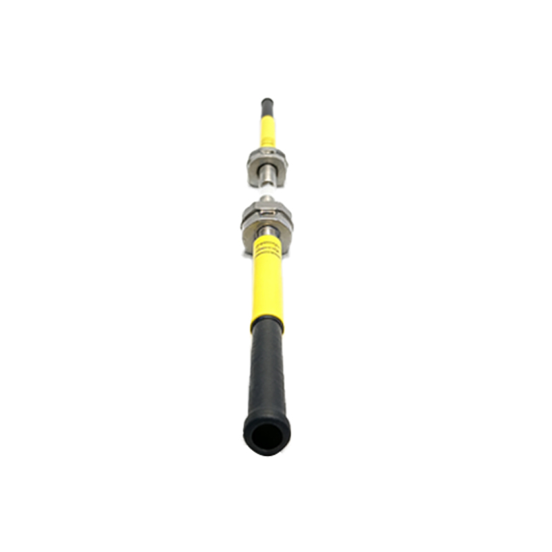
Before wiring, locate the terminal configuration on the N1211. Standard models feature three or four wires: brown (positive power supply), blue (negative power supply), black (normally open output), and white (normally closed output) if present. The supply voltage is typically 10-30V DC. Always refer to the datasheet for your specific variant, as some models may have different color codes or include an additional wire for testing or synchronization.
Power Supply Connection
Connect the brown wire to the positive terminal of your DC power supply (e.g., +24V) and the blue wire to the negative terminal (0V). Ensure the power supply is properly filtered and stabilized to avoid voltage spikes that could damage the sensor. Use a fuse rated at 500mA for protection. The sensor is polarity-sensitive, so verify connections with a multimeter before powering on.
Output Wiring for NPN or PNP Configurations
The N1211 is available in both NPN (sinking) and PNP (sourcing) output types. For PNP models, the black wire (normally open) connects to the load (e.g., PLC input) and the load’s other terminal to 0V. For NPN models, the black wire connects to the load and the load’s other terminal to +V. If your sensor has a white wire (normally closed), it works oppositely. Use pull-up or pull-down resistors (typically 10kΩ) if required by your controller.
Wiring to a PLC Input Module
When connecting to a PLC, match the sensor output type to the input module. For a sinking input module, use a PNP sensor: connect sensor output to input terminal, and input common to 0V. For a sourcing input module, use an NPN sensor: connect sensor output to input, and input common to +V. Always add a 0.5A fuse in series and check the PLC’s input impedance to prevent overcurrent.
Grounding and Shielding Best Practices
To minimize electrical noise, use a shielded cable for the sensor wiring, especially in environments with motors or variable frequency drives. Connect the shield drain wire to the earth ground at the controller side only, not at the sensor. Keep sensor cables separate from power lines to avoid electromagnetic interference. Test continuity of the ground connection with an ohmmeter.
Testing and Troubleshooting
After wiring, power on the system and use a multimeter to check voltage at the sensor terminals (should match supply). Test the output by blocking the sensor beam: the black wire voltage should toggle between 0V and supply voltage. If no response, verify the output type (PNP/NPN), check for loose connections, and ensure the sensor lens is clean. Common issues include reversed polarity or incorrect load wiring.
Safety Precautions
Always disconnect power before wiring or modifying connections. Wear insulated gloves and use tools rated for electrical work. Verify that the sensor’s operating voltage matches your system. Do not exceed the maximum load current (typically 100mA) as this may damage the sensor. Follow local electrical codes and regulations for installation.