Introduction to Through-Beam Photoelectric Sensors
Through-beam photoelectric sensors are widely used in industrial automation for precise object detection. They consist of a separate emitter and receiver, ensuring high reliability and long sensing distances. The four-pin configuration is a standard interface that simplifies wiring and integration into control systems. Each pin serves a specific function: power supply, ground, output signal, and often an additional control or test line. Understanding these pins is crucial for proper installation and troubleshooting.
Pin 1: Power Supply (Vcc)
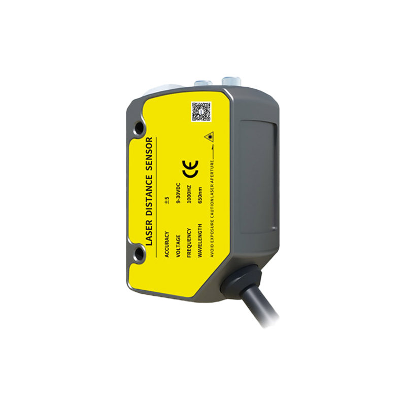
The first pin typically connects to the positive voltage supply, often ranging from 10 to 30 VDC depending on the sensor model. This pin powers the internal electronics of the emitter and receiver modules. Engineers must ensure the supply voltage matches the sensor specifications to avoid damage. In many industrial setups, a regulated DC power source is used, and this pin is usually color-coded brown in wiring diagrams.
Pin 2: Ground (GND)
The second pin is the common ground terminal, connecting to the negative side of the power supply. Proper grounding is essential for noise immunity and stable operation. In environments with high electromagnetic interference, a dedicated ground wire helps maintain signal integrity. This pin is often color-coded blue in standard wiring conventions.
Pin 3: Output Signal (Out)
The third pin provides the digital output signal, typically a PNP or NPN transistor switch. When the light beam from the emitter is interrupted by an object, the output changes state—either from high to low or vice versa, depending on the sensor’s light-on or dark-on mode. This pin connects to a PLC input or relay for further processing. In some models, the output may include a short-circuit protection feature.
Pin 4: Test or Control Input (Optional)
The fourth pin is often a test input or control line, allowing external triggering or diagnostics. For example, applying a voltage to this pin can temporarily disable the sensor for calibration or system checks. Not all through-beam sensors include this pin; in simpler designs, it may be left unconnected. When present, it offers added flexibility for maintenance and testing without removing the sensor from the system.
Wiring Best Practices
When wiring a four-pin through-beam sensor, always refer to the manufacturer’s datasheet for specific pin assignments and color codes. Use shielded cables for long runs to reduce electrical noise. Ensure the power supply is off during installation to prevent short circuits. After connecting, test the sensor with a known object to confirm proper output behavior. Regular inspection of the pins for corrosion or loose connections extends sensor life in harsh industrial environments.
Common Applications and Troubleshooting
These sensors excel in applications requiring long-range detection, such as conveyor belt monitoring, door control, and material handling. If the sensor fails to detect objects, check the alignment between emitter and receiver, verify power at the pins, and examine the output signal with a multimeter. A common issue is miswiring of the output pin to the wrong input type (e.g., NPN vs PNP), so confirm compatibility with the control system. Proper pin identification ensures reliable operation and minimizes downtime.