Understanding the Photoelectric Sensor and Its Role in the Chamber
In industrial temperature-controlled chambers (often referred to as constant temperature chambers or incubators), photoelectric sensors are used for precise object detection, such as monitoring sample presence or door status. These sensors typically consist of an emitter and receiver, using light to detect changes. For example, a through-beam sensor detects when an object breaks the beam, while a reflective sensor relies on light reflection from the target. The wiring diagram must ensure the sensor operates reliably under varying temperature and humidity conditions, as chamber environments can stress components. Always verify the sensor’s voltage rating (e.g., 10-30 VDC) and output type (NPN or PNP) before proceeding.

Essential Components and Tools for Wiring
Before starting, gather the following: the photoelectric sensor (with datasheet), a shielded cable (e.g., 4-core, 0.5 mm²), a 24 VDC power supply (typical for most sensors), a load (e.g., PLC input or relay), wire strippers, a multimeter, and heat shrink tubing. For chambers with high humidity, use IP67-rated connectors to prevent moisture ingress. The wiring diagram will often include four wires: brown (positive), blue (negative), black (output), and white (or gray, for complementary output). Ensure all components are rated for the chamber’s operating range (e.g., -10°C to 60°C).
Step-by-Step Wiring Diagram for NPN Output Sensors
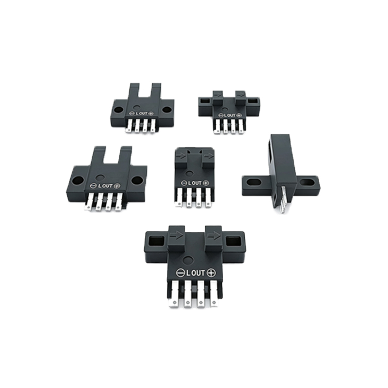
An NPN sensor acts as a current sink, meaning it connects the load to ground when activated. Follow this configuration: 1. Connect the brown wire to the positive terminal of the 24 VDC power supply. 2. Connect the blue wire to the negative terminal (0V). 3. Connect the black wire to one side of the load (e.g., PLC input), and the other side of the load to the positive terminal of the power supply. 4. If the sensor has a white wire for complementary output (e.g., normally open or closed), refer to the datasheet—typically it connects similarly but with an inverted logic. For a chamber with a door monitoring application, the sensor’s black wire should be wired to the PLC’s digital input module, ensuring a pull-up resistor is used if required.
Step-by-Step Wiring Diagram for PNP Output Sensors
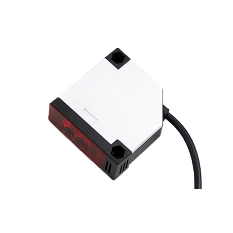
A PNP sensor acts as a current source, providing power to the load when activated. The wiring differs: 1. Brown wire to the positive terminal of the 24 VDC supply. 2. Blue wire to the negative terminal. 3. Black wire connects to one side of the load, and the other side of the load connects to the negative terminal of the power supply. 4. The white wire, if present, serves as the complementary output and can be wired similarly but with opposite logic. For a chamber using a through-beam sensor to detect sample trays, this configuration ensures the PLC receives a high signal when the beam is broken. Always test the output with a multimeter before finalizing connections.
Common Mistakes and Troubleshooting in Chamber Environments
One frequent error is misidentifying the sensor output type, leading to reverse wiring and no signal. Use a multimeter to measure voltage between the black wire and negative (for PNP) or positive (for NPN) when the sensor is triggered. Another issue is cabling interference; in a chamber with motors or heaters, use shielded cables and connect the shield to ground at one end only to avoid ground loops. Temperature fluctuations can cause thermal drift in the sensor, so check the datasheet for temperature compensation. If the sensor fails to detect objects clearly, clean the lens and adjust the sensitivity potentiometer (if available). For high-humidity chambers, ensure all connections are sealed with silicone-based compound.
Final Verification and Safety Precautions
After wiring, power up the system and test the sensor function through the chamber’s control interface. Confirm that the output voltage matches the expected logic (e.g., +24V for PNP triggered state, 0V for NPN). Include a fuse (e.g., 0.5A) on the power supply line to protect against short circuits. Always disconnect power before adjusting wires. In the event of a chamber with explosive atmospheres, use intrinsically safe barriers. Document the wiring diagram with component labels for future maintenance. Remember to follow local electrical codes and the chamber manufacturer’s guidelines.