Introduction to Infrared Photoelectric Sensors in Proteus
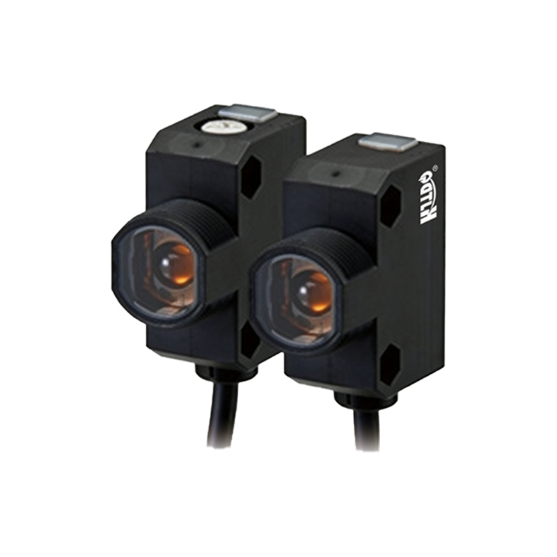
Infrared photoelectric sensors are critical components in modern electrical engineering systems, enabling non-contact detection of objects based on infrared light reflection or interruption. When simulated within the Proteus design suite, these sensors allow engineers to validate circuit behavior before physical prototyping. The sensor typically consists of an infrared LED (IR LED) as the emitter and a phototransistor or photodiode as the receiver. In Proteus, you can model this using standard components like a generic IR LED and an NPN phototransistor. The simulation environment provides real-time analysis of voltage changes across the receiver, which directly correlates to the presence or absence of an obstacle. This section outlines the fundamental operating principle and its relevance in educational and industrial design verification.
Component Selection and Circuit Configuration
For an accurate Proteus simulation, select the IR LED (e.g., LED-IR from the library) and a phototransistor (e.g., TIL78 or a generic phototransistor model). The emitter circuit should include a current-limiting resistor (typically 100-220 ohms) in series with the IR LED, driven by a 5V DC source. The receiver circuit uses the phototransistor with a collector load resistor (e.g., 10k ohms) connected to VCC, and the emitter grounded. The output voltage is taken from the collector node. Ensure the IR LED wavelength is set to 940 nm in its properties to match standard infrared sensors. This configuration allows the phototransistor to conduct when it detects reflected IR light, dropping the collector voltage. Carefully set the phototransistor's sensitivity parameters (such as gain) in the component model to achieve realistic behavior. For obstacle detection, position the IR LED and phototransistor side-by-side facing the same direction, mimicking a reflective sensor module.
Simulation Setup and Performance Analysis
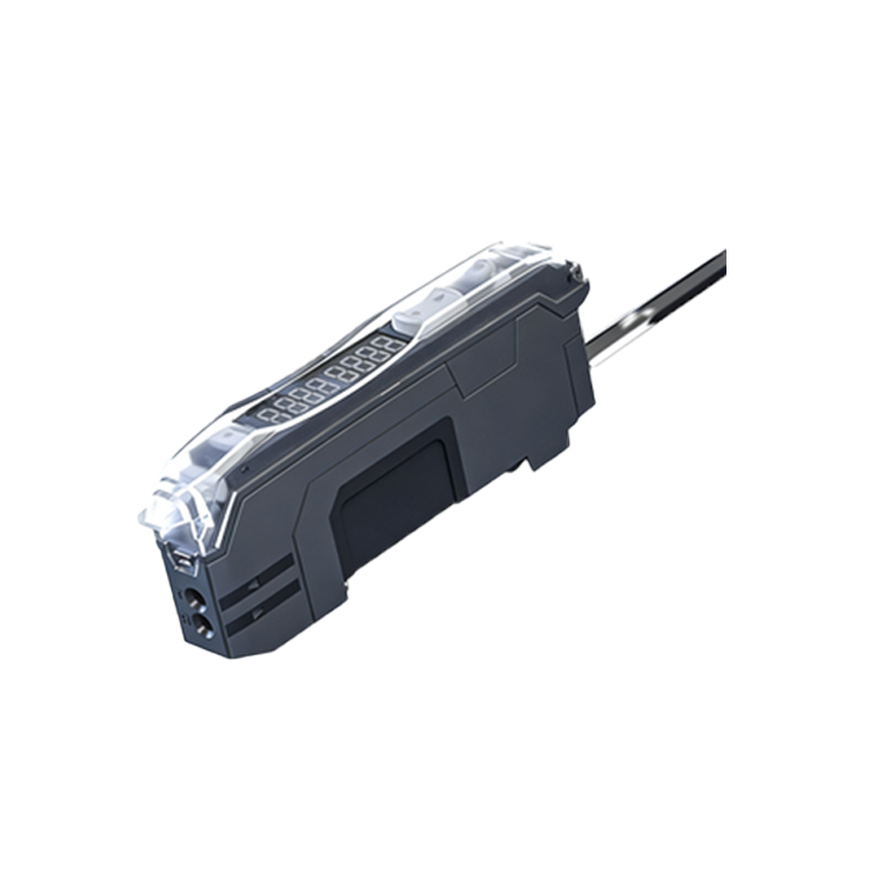
In Proteus, place the components on a schematic sheet and connect them as per the circuit design. Add a digital oscilloscope (e.g., OSCILLOSCOPE) to monitor the collector voltage. Use a square wave generator to simulate modulated IR emission if needed, but for basic detection, a constant DC drive works. Run the simulation and observe the output. When no object is present, the phototransistor remains off, and the collector voltage stays near VCC (5V). Introduce a reflective surface (like a piece of white paper) near the sensor pair; the IR light reflects onto the phototransistor, turning it on and dropping the collector voltage to near 0V. Analyze the response time and voltage swing. For accuracy, adjust the resistor values or the phototransistor's gain. You can also use a virtual terminal to log the digital output from a comparator (like LM393) connected to the collector, converting the analog signal into a clear high/low logic level for microcontroller interfaces.
Practical Applications and Engineering Insights
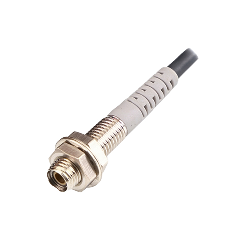
The simulated infrared photoelectric sensor has numerous real-world applications, including object counting, line-following robots, and proximity detection in industrial automation. In Proteus, engineers can integrate this sensor with microcontrollers like PIC or Arduino models to develop feedback control systems. For example, link the comparator output to an interrupt pin of a microcontroller to trigger a counter when an object passes. The simulation helps identify issues like ambient light interference or detection range limitations. Adjust the IR LED drive current or add a lens model in the simulation to explore focusing effects. This approach reduces hardware iteration costs and accelerates development cycles. Electrical engineering professionals use such simulations to teach sensor principles, debug circuit designs, and test firmware logic before PCB fabrication.
Troubleshooting and Optimization Tips
Common simulation issues include the phototransistor failing to switch or producing a weak signal. First, verify that the IR LED is emitting by checking its current (e.g., 10-20 mA). Increase the phototransistor's collector resistor (e.g., to 47k ohms) to amplify the voltage drop. If using a reflective object, ensure its surface has high infrared reflectivity (e.g., white cardboard) and place it within 5-10 cm. In Proteus, the phototransistor model may have a default low gain; modify its forward current transfer ratio (hFE) to 500-1000 in its component properties. Add a Schmitt trigger circuit (e.g., using a 74HC14 inverter) to clean up the output signal and avoid noise. Finally, use a decoupling capacitor (100 nF) across the power supply to stabilize the simulation. These optimizations ensure reliable sensor operation in both virtual and physical prototypes.