Introduction to Photoelectric Sensors in Speed Measurement
Photoelectric sensors are essential components in modern industrial automation, widely used for non-contact speed measurement of rotating and moving objects. These sensors operate by emitting a beam of light, typically infrared or visible, and detecting changes in the reflected or interrupted signal. In speed measurement applications, a photoelectric sensor is often paired with a rotating target, such as a slotted disk or reflective tape, to generate a pulse train. The frequency of these pulses directly correlates to the rotational speed, allowing engineers to calculate RPM (revolutions per minute) or linear velocity with high precision.
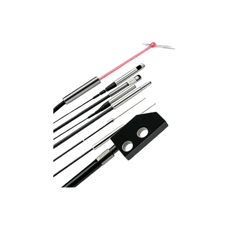
Key Components of a Photoelectric Sensor Speed Measurement Setup
A typical speed measurement system using a photoelectric sensor includes the sensor head, a target, a controller, and a display or data acquisition unit. The sensor head contains an emitter and a receiver, which can be configured in through-beam, retro-reflective, or diffuse modes. For speed measurement, retro-reflective sensors are common, as they rely on a reflector to return the light beam. The target, such as a toothed wheel or a patterned disk, interrupts or reflects the beam, creating electrical pulses. The controller processes these pulses, often using a frequency-to-voltage converter or a microcontroller, to output a speed value.
Interpreting the Speed Measurement Diagram
A photoelectric sensor speed measurement diagram typically illustrates the relationship between the sensor, target, and signal output. The diagram shows the sensor positioned at a fixed distance from the target, with the light beam intersecting the target's path. As the target rotates, the diagram highlights the changing states of the beam: blocked or unblocked. The output signal is a square wave, where the period of the wave corresponds to the time between successive beam interruptions. Engineers use the formula: Speed (RPM) = (60 * f) / N, where f is the pulse frequency in Hz and N is the number of pulses per revolution. The diagram often includes a timing chart to visualize this relationship.
Practical Considerations for Accurate Speed Measurement
Achieving accurate speed measurement requires careful selection of sensor type, target design, and installation parameters. The sensor's response time must be fast enough to capture high-speed pulses; for example, a sensor with a 1 kHz switching frequency is suitable for up to 60,000 RPM with a 1-pulse-per-revolution target. Environmental factors such as dust, vibration, and ambient light can affect performance, so choosing sensors with high immunity is critical. Additionally, the target's pattern must ensure consistent pulse generation, avoiding non-uniform spacing that could introduce errors. Calibration using a known speed source is recommended to verify system accuracy.
Common Applications and Troubleshooting Tips
Photoelectric sensor speed measurement is employed in conveyor belts, motor speed monitoring, and turbine blade inspection. For example, in a conveyor system, sensors detect the movement of products to calculate line speed. Common issues include pulse jitter due to target misalignment, false triggers from reflective background surfaces, and signal loss from sensor lens contamination. Troubleshooting involves verifying sensor alignment, cleaning optics, and adjusting the sensitivity threshold. Using a shielded cable and proper grounding can reduce electrical noise interference, ensuring reliable pulse detection.
Conclusion: Leveraging Diagrams for System Optimization
Understanding photoelectric sensor speed measurement diagrams empowers engineers to design robust systems for real-time monitoring and control. By analyzing the diagram's signal patterns, technicians can diagnose issues, optimize target geometry, and select appropriate sensor models. This knowledge is vital for industries requiring precise speed regulation, such as automotive manufacturing and packaging. Regularly updating the sensor setup based on diagram insights helps maintain operational efficiency and reduce downtime.