Understanding the NPN Output in Photoelectric Sensors
In electrical engineering, the NPN output configuration is a common choice for photoelectric sensors, particularly in industrial automation. NPN, or sinking output, provides a low-side switch that connects the load to ground when the sensor is activated. For video testing, it is crucial to verify that the sensor's NPN transistor can properly sink current, typically within a range of 0 to 100 mA, depending on the model. The test setup should include a power supply (e.g., 12-24 VDC), a multimeter, and an oscilloscope for waveform analysis. Ensure the sensor's power terminals are correctly connected to the positive and negative rails, and the output pin is linked to a pull-up resistor to a logic voltage (e.g., 5 V or 10 V) for stable signal detection.
Setting Up the Video Monitoring Environment
To accurately capture performance, a high-speed camera or video recorder with at least 1000 frames per second is recommended to observe transient responses. Position the sensor in a controlled lighting environment, using a standard obstruction (e.g., a white or black target) to trigger the NPN output. Connect the video system to the sensor's output via a BNC-to-oscilloscope adapter to record both the voltage waveform and the physical event. Calibrate the exposure to ensure the target's movement is clear, and set the recording duration to at least 10 seconds to capture multiple cycles. This setup allows engineers to analyze delay, rise time, and fall time in the NPN signal.
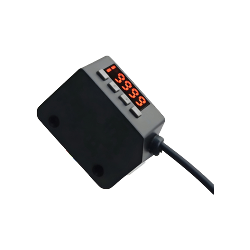
Conducting the NPN Output Test Sequence
Begin by applying power to the sensor and verifying the quiescent state: the NPN output should be high (due to the pull-up resistor) when no target is present. Introduce the target at a known distance, typically 50 mm for standard sensors, and record the video. Use the oscilloscope to measure the voltage drop from high to low (0 V) as the sensor activates. Key parameters include response time (typically under 1 ms for fast sensors), hysteresis, and repeatability. Test at least 50 cycles to ensure statistical significance, noting any jitter or false triggers. For video analysis, overlay the oscilloscope trace with the frame-by-frame video to correlate the optical event with the electrical signal.
Analyzing Waveform Integrity and Noise
After data collection, examine the NPN waveform for integrity. A clean NPN signal should show a sharp transition from the high state (e.g., 10 V) to low (0 V) with minimal ringing or overshoot. Use the oscilloscope's FFT function to check for noise at 50/60 Hz or higher frequencies from ambient light interference. In the video, look for any lag between the target crossing the beam and the signal change. If the rise time exceeds 5 µs or the fall time exceeds 10 µs, consider adjusting the pull-up resistor value (e.g., from 10 kΩ to 1 kΩ) to improve speed. Document all anomalies, such as incomplete saturation (output not reaching 0 V) which indicates a defective transistor.
Interpreting Results for Industrial Applications
The final step is to interpret the video and waveform data for practical use. For NPN sensors in PLC inputs, the output must maintain a low impedance (below 1 Ω) when active to ensure reliable sinking. Compare your measured rise/fall times against the datasheet specifications; for instance, a typical photoelectric sensor should have a response time under 500 µs. If the video shows inconsistent triggering, check the target's reflectivity or the sensor's sensitivity adjustment. Present results in a report with graphs showing time delay distribution, and recommend sensor replacement if failure rates exceed 1% per 1000 cycles. This test validates the sensor for use in conveyor belt control, object counting, or safety systems.