Understanding the Role of DIP Switches in Slot-Type Photoelectric Sensors
In industrial automation, slot-type photoelectric sensors are widely used for object detection, counting, and positioning in conveyor systems, packaging machines, and assembly lines. These sensors often come with a set of DIP switches that allow engineers to configure key parameters such as output type, light-on/dark-on mode, response time, and sensitivity. Properly setting these switches ensures reliable detection and minimizes false signals in harsh environments. Unlike software-based configuration, DIP switches provide a hardware-level, low-cost solution that is easy to adjust on-site without requiring a programmer or specialized tools.
Common DIP Switch Configurations and Their Functions
Most slot-type sensors feature a 4- or 8-position DIP switch block. The most common settings include:
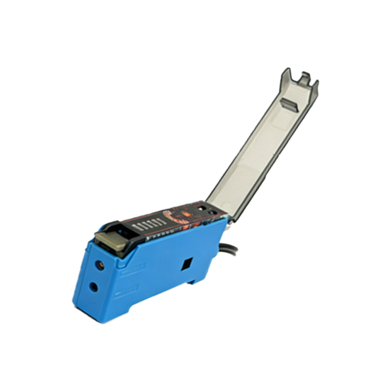
- Output Type: Select NPN (sinking) or PNP (sourcing) based on your PLC or controller input requirements. Incorrect selection may cause no signal or damage.
- Light-On/Dark-On Mode: Choose whether the output activates when the light beam is uninterrupted (light-on) or blocked (dark-on). This is critical for detecting transparent objects or reflective surfaces.
- Response Time: Faster response (e.g., 1 ms) is ideal for high-speed applications, while slower response (e.g., 10 ms) reduces noise in vibration-prone environments.
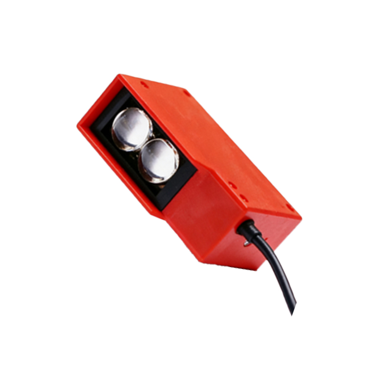
- Sensitivity Adjustment: Some switches offer coarse sensitivity levels to adapt to different object colors, sizes, or environmental dust.
Always refer to the sensor’s datasheet for the exact pinout and function of each switch position, as layouts vary by manufacturer.
Step-by-Step Procedure for Setting DIP Switches
1. Power Off: Always disconnect the sensor from power before changing switch positions to prevent short circuits or unintended operation.
2. Identify the Switch Block: Locate the DIP switch block, usually on the sensor’s side or bottom. It may be covered by a small rubber cap for dust protection.
3. Select Output Type: For most PLCs, PNP (sourcing) is common in Europe and Asia, while NPN (sinking) is frequent in North America. Match your system logic.
4. Choose Mode: If detecting opaque objects in a clean environment, use light-on. For transparent objects or high dust levels, dark-on often yields better stability.
5. Set Response Time: Use the fastest response for high-speed counting. For heavy vibration, select a slower response to filter out false pulses.
6. Toggle Switches: Use a small screwdriver or a dedicated tool to move each switch to ON or OFF. Avoid excessive force to prevent damage.
7. Power On and Test: Reconnect power and test with a sample object. Verify output signal with a multimeter or indicator LED on the sensor.
Troubleshooting Common Issues with DIP Switch Settings
- No Output Signal: Check if the output type (NPN/PNP) matches the load. Also confirm the mode (light-on/dark-on) is correctly set.
- False Triggering: Increase response time or adjust sensitivity. Dust or ambient light interference may require a different mode.
- Intermittent Detection: Ensure all switches are fully toggled to their intended position. Partial engagement can cause erratic behavior.
- Overheating: If the sensor runs hot, the output type may be wrong, causing excessive current draw.
If problems persist, swap the sensor with a known-good unit to rule out hardware failure.
Best Practices for Long-Term Reliability
- Document the DIP switch settings for each sensor in your system, especially for critical applications. Use label stickers near the switch block.
- Use a protective cover or sealant over the switch block if the sensor is exposed to moisture, oil, or dust.
- Regularly verify settings during preventive maintenance, as vibrations can slowly shift switches over time.
- Train maintenance staff on the correct procedure to avoid accidental changes during cleaning or replacement.
Proper DIP switch configuration is a simple yet powerful way to adapt slot-type photoelectric sensors to diverse industrial conditions. By following these guidelines, you can ensure stable, accurate detection and reduce downtime.