Introduction to Photoelectric Sensors
Photoelectric sensors are fundamental components in industrial automation, used for detecting objects, distances, or presence without physical contact. They operate by emitting a beam of light and measuring its reflection, interruption, or absorption. In electrical schematics, these sensors are represented by standardized symbols that convey their function and wiring configuration. Understanding these symbols is crucial for engineers designing control systems, troubleshooting installations, or reading technical drawings.
Basic Symbol Components
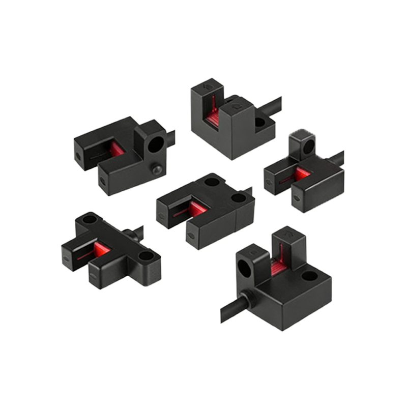
The core symbol for a photoelectric sensor typically consists of a rectangle or circle representing the sensor housing, with arrows indicating the light beam direction. A common variant includes a triangle or LED icon to denote the emitter, and a phototransistor or photodiode symbol for the receiver. For through-beam sensors, two separate symbols are used: one for the emitter and one for the receiver, often labeled as "Tx" (transmitter) and "Rx" (receiver). In contrast, retro-reflective sensors feature a single symbol with a beam arrow pointing to a reflector, while diffuse sensors show a beam ending with a curved line to indicate scattered reflection.
Power Supply and Output Connections
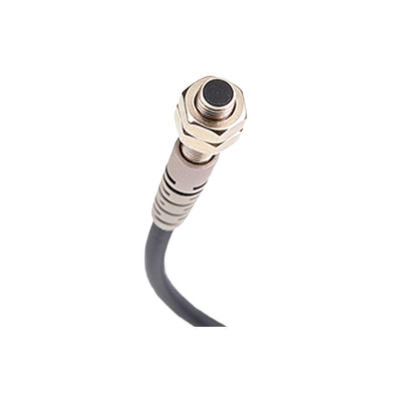
Schematic symbols must also indicate the power supply and output type. A typical photoelectric sensor symbol includes pins for VCC (positive voltage), GND (ground), and output (OUT). The output may be represented as a normally open (NO) or normally closed (NC) contact, often shown as a switch inside the symbol. For NPN (sinking) outputs, the output line connects to ground when activated; for PNP (sourcing) outputs, it connects to VCC. These differences are denoted by additional symbols like a small arrow or transistor icon within the sensor block.
Common Variations in Industry Standards
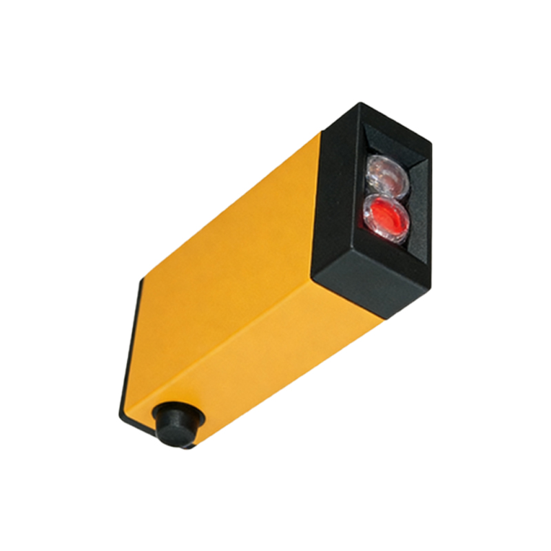
Different industries and regions may use slight variations in photoelectric sensor symbols. The International Electrotechnical Commission (IEC) standard often uses a rectangular box with internal symbols for light source and detector, while the National Electrical Manufacturers Association (NEMA) may employ more detailed diagrams. In practice, engineers frequently encounter symbols that combine a rectangle with a lens icon and labeled terminals. For example, a fiber optic sensor symbol might include a small circle with a dashed line representing the fiber cable. Understanding these variants ensures accurate interpretation of drawings from multiple manufacturers.
Practical Application in Wiring Diagrams
When reading a wiring diagram, the photoelectric sensor symbol is integrated into the control circuit. For instance, a through-beam sensor symbol may appear as two separate blocks connected by a dashed line representing the light path. The emitter block has a power terminal and a common terminal, while the receiver block includes output and ground. In automated systems, these symbols are linked to PLC inputs or relay coils. Correctly identifying the symbol helps engineers verify that the sensor is wired for correct polarity and output type, preventing installation errors.
Conclusion and Best Practices
Mastering photoelectric sensor schematic symbols is essential for efficient industrial design and maintenance. Engineers should always refer to the manufacturer's datasheet for specific symbol details, as variations exist between brands. When creating schematics, use clear labels for emitter and receiver, and clearly indicate output type (NPN/PNP). This practice enhances readability and reduces risks of miswiring. Regular training on symbol standards, such as IEC and NEMA, is recommended for engineering teams to ensure consistency across projects.