Understanding Baumer Photoelectric Sensor Wiring Basics
As an electrical engineer in the automation industry, I often encounter installation challenges with Baumer photoelectric sensors. These sensors, known for their precision and reliability, require correct wiring to ensure optimal performance. The standard wiring configuration typically involves three to five wires: brown for positive power supply (+24V DC), blue for negative (0V), and black for the output signal. For models with additional features, such as teach-in or alarm outputs, white and gray wires may be present. Always reference the specific datasheet for your sensor model, as pin assignments can vary between series like the O300 or O500. Use shielded cables in noisy environments to minimize electromagnetic interference, and ensure wire stripping lengths do not exceed 8mm to prevent short circuits.
Pre-Wiring Checklist and Safety Precautions
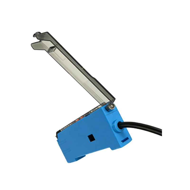
Before beginning the wiring process, power off the entire system to avoid electrical shock or damage to the sensor. Verify that the power supply voltage matches the sensor’s specifications, typically 10-30V DC for most Baumer models. Check the sensor’s output type—PNP (sourcing) or NPN (sinking)—and ensure compatibility with your PLC or controller input. For example, PNP outputs are common in European systems, while NPN is prevalent in Asian applications. Use a multimeter to test continuity on cables and confirm that no wires are damaged. Additionally, inspect the sensor’s housing for cracks or debris, as contaminants can affect sealing and performance. Properly grounding the system is critical; connect the shield wire only at the controller end to avoid ground loops.
Step-by-Step Wiring Procedure for Standard Baumer Sensors
Begin by stripping the cable jacket carefully, exposing the individual wires without nicking the conductors. For a three-wire PNP sensor, connect the brown wire to the positive terminal of the power supply, the blue wire to ground, and the black wire to the input of your PLC or relay. If using an NPN sensor, the wiring remains similar, but the black output will sink to ground when activated. For sensors with a teach-in function, such as the Baumer O200 series, the white wire is used for programming. Connect it momentarily to ground or positive voltage as specified in the manual. After making connections, use wire ferrules to secure stranded wires in terminal blocks, preventing loose contacts. Double-check all connections with a wiring diagram before powering on the system.
Common Wiring Mistakes and Troubleshooting Tips
One frequent issue is reverse polarity, which can damage the sensor irreparably. Always confirm that the brown wire is on the positive rail. Another mistake is using an incorrect load; for example, connecting a PNP output directly to a high-current device without a proper resistor can cause overheating. If the sensor fails to trigger, check the output voltage with a multimeter—it should switch between 0V and supply voltage. For intermittent signals, inspect for cable strain or bends at the connector, as Baumer sensors are sensitive to excessive flexing. In harsh environments, seal all connections with IP67-rated connectors to prevent moisture ingress. If problems persist, verify that the sensor’s sensing distance is not affected by background objects or reflective surfaces.
Advanced Wiring: Connecting Multiple Sensors in a Network
For complex automation systems, Baumer sensors can be daisy-chained using M12 connectors with Y-cables. This setup reduces wiring complexity but requires careful current budgeting. Each sensor typically draws 10-30mA, so ensure the total current does not exceed the power supply rating. Use IO-Link communication for advanced diagnostics; this requires a dedicated IO-Link master and a four-wire cable (power plus data lines). Configure the sensor’s parameters, such as switching frequency or output logic, via the master software. When wiring multiple sensors, maintain equal cable lengths to avoid timing delays. Label each cable clearly at both ends for future maintenance, and test each sensor individually before integrating into the control system.