1. Power Supply Issues
The most fundamental cause for all photoelectric sensors failing is a power supply problem. Check the voltage at the sensor terminals with a multimeter. Ensure the power source matches the sensor's rated voltage (e.g., 12-24 VDC or 24-240 VAC). Look for tripped circuit breakers, blown fuses, or loose wiring connections. In industrial environments, voltage drops due to long cable runs can also cause sensors to malfunction. Verify the power supply is stable and free from excessive ripple or noise.
2. Environmental Contamination
Industrial settings often expose sensors to dust, oil, coolant, or condensation on the lens or reflector. For through-beam and retro-reflective sensors, even a thin film of contamination can block or diffuse the light beam, causing a false 'no object' state. Clean all optical surfaces with a soft, lint-free cloth and isopropyl alcohol. Check for buildup on the emitter and receiver windows. For diffuse sensors, contamination can reduce the sensing range significantly.
3. Misalignment of Optical Path
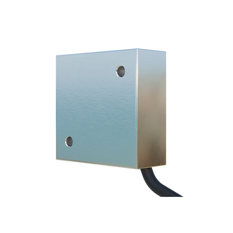
If the sensor is mounted on a vibrating machine or was bumped during maintenance, the emitter and receiver may be out of alignment. For through-beam sensors, the emitter and receiver must be precisely aligned. For retro-reflective sensors, the reflector must be perpendicular to the beam. Use an alignment tool or a piece of white paper to verify the beam path. Re-adjust the mounting brackets and tighten all fasteners. Consider using vibration-dampening mounts for high-vibration areas.
4. Ambient Light Interference
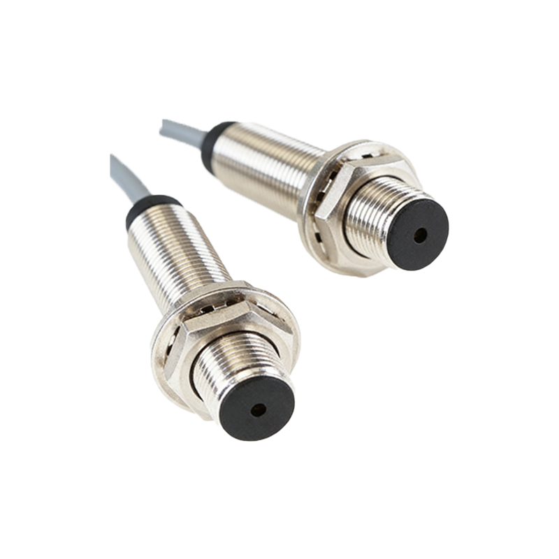
High-intensity ambient light, especially from welding arcs, strobes, or direct sunlight, can overwhelm the sensor's receiver. Photoelectric sensors use modulated light to filter out steady ambient light, but pulsed sources can cause false triggers. Shield the sensor with a hood or relocate it away from direct light sources. Alternatively, switch to a sensor with a different modulation frequency or use a polarizing filter for retro-reflective models.
5. Incorrect Wiring or Polarity
Verify the wiring diagram for your specific sensor model. Common mistakes include swapping the output and power wires, or reversing polarity on DC sensors (which can damage the sensor). Check for broken wires, especially near cable entry points or in cable tracks. Use a continuity tester to verify each wire from the sensor to the controller. For three-wire sensors, ensure the load is properly connected between the output and the common terminal.
6. Object and Background Issues
For diffuse sensors, the target object may not reflect enough light. Shiny or black objects reflect poorly. Test with a white piece of paper to confirm the sensor works. Also, check if the background is too reflective, causing the sensor to 'see' the background instead of the object. Adjust the sensitivity pot (if available) or switch to a background suppression sensor. For retro-reflective sensors, ensure the reflector is clean and not damaged.
7. Sensor Internal Failure
After all external checks, the sensor itself may be faulty. Check for physical damage like cracked lenses or corroded terminals. Use a spare known-good sensor to swap-test on the same mounting position and wiring. If the spare works, the original sensor needs replacement. Note that some sensors have a limited lifespan due to LED degradation, especially in high-temperature environments.
8. Controller or PLC Input Issues
The sensor might be working, but the controller input is faulty. Check the input module's status indicator. Use a multimeter to measure the voltage at the controller input terminal when the sensor is activated. For NPN sensors, the output goes low (near 0V); for PNP, it goes high (near supply voltage). If the sensor output is correct but the PLC doesn't see it, check the input wiring and module configuration.