Introduction to Photoelectric Counting Sensors
Photoelectric sensors are essential components in industrial automation, used for detecting objects, counting products, and triggering actions. As an electrical engineer, constructing a custom counting photoelectric sensor allows for tailored performance, cost savings, and deeper understanding of optoelectronic systems. This guide details the design, component selection, circuit assembly, and calibration of a through-beam photoelectric sensor optimized for high-speed counting tasks.
Core Components and Circuit Design
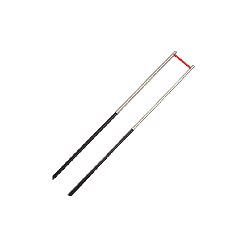
The sensor system comprises an infrared LED (940nm wavelength) as the emitter, a phototransistor (e.g., TEPT5700) as the receiver, and a comparator circuit (LM393) for signal conditioning. The emitter circuit includes a current-limiting resistor (typically 100Ω for 20mA LED drive) and a transistor switch for pulsed operation to reduce power consumption and improve immunity to ambient light. The receiver circuit connects the phototransistor in a voltage divider configuration with a 10kΩ load resistor, feeding into the comparator’s non-inverting input. A reference voltage is set via a potentiometer (10kΩ) on the inverting input to adjust sensitivity.
Signal Processing and Noise Filtering
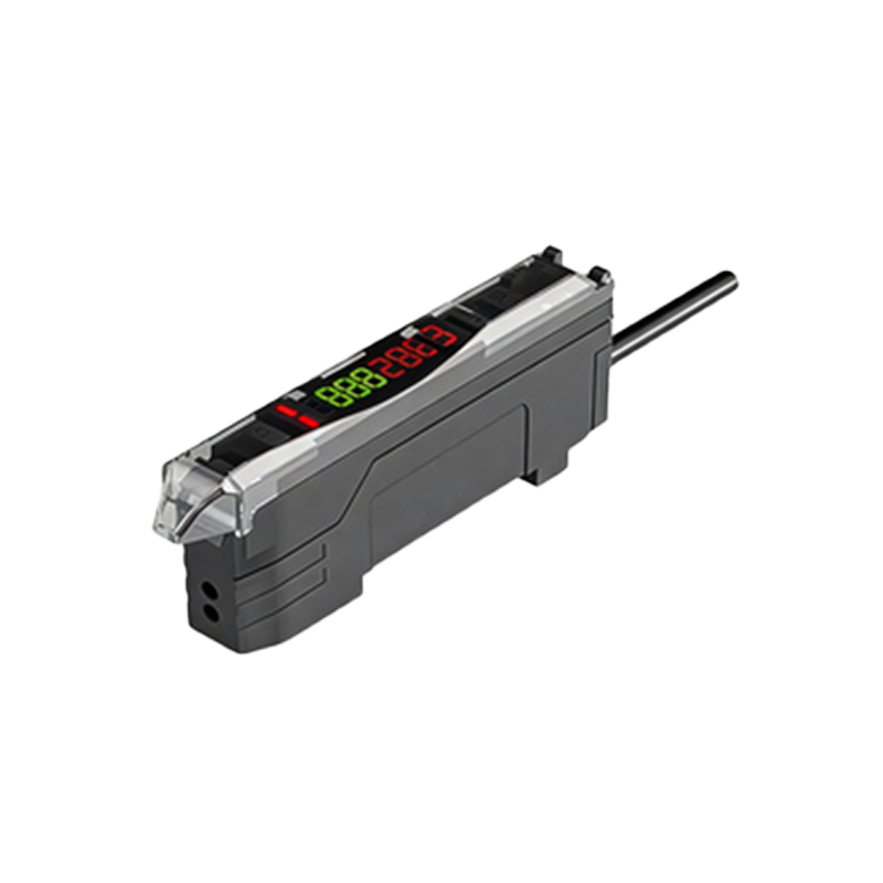
Raw signals from the phototransistor often contain noise from electrical interference or fluctuating ambient light. To address this, implement a Schmitt trigger using positive feedback via a 100kΩ resistor from the comparator output to the non-inverting input. This hysteresis (approximately 50mV) ensures clean, bounce-free transitions. Additionally, a low-pass RC filter (10kΩ resistor + 1µF capacitor) at the receiver output attenuates high-frequency noise before the comparator. For counting applications, the comparator output is connected to a microcontroller (e.g., Arduino Nano) interrupt pin, enabling event-driven counting without polling overhead.
Optical Alignment and Mechanical Assembly
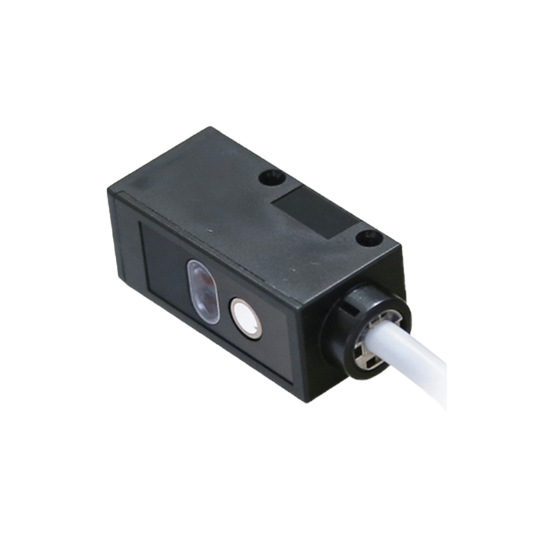
Physical alignment between emitter and receiver is critical for reliable detection. Mount both components using custom 3D-printed brackets or aluminum profiles, ensuring coaxial alignment within 1mm tolerance. The emitter-receiver distance should not exceed 500mm for stable operation; for longer ranges, use collimating lenses (e.g., plano-convex with 10mm focal length) to narrow the beam. Include a protective enclosure (IP65 rated) to shield optics from dust and moisture. For counting small parts, position the sensor at the edge of a conveyor belt, using a reflective surface if a through-beam setup is impractical.
Calibration and Testing Procedure
After assembly, calibrate the sensor using a known object (e.g., 10mm diameter metal disk). Start with the potentiometer set to mid-range, then adjust until the comparator output toggles cleanly when the object passes through the beam. Use an oscilloscope to verify the output waveform: a clean square wave with rise/fall times under 1µs indicates proper hysteresis and noise immunity. Test counting accuracy by running 1000 objects at a speed of 10 pieces/second. Acceptable error is less than 0.1% (i.e., 1 miscount per 1000). If miscounts occur, reduce the comparator reference voltage slightly or increase hysteresis via a larger feedback resistor.
Integration with Industrial Control Systems
For real-world deployment, connect the sensor output to a PLC digital input module (24V DC sink/source compatible). If using microcontroller output, add a level shifter (e.g., 5V to 24V using a transistor driver) to match industrial voltage levels. Implement a debounce routine in the PLC ladder logic (e.g., 5ms delay filter) to handle contact chatter. For high-speed counting (over 100 Hz), consider using a dedicated hardware counter module instead of software-based counting to prevent data loss. Finally, document the sensor’s response time (typically 10-20µs) and maximum object speed in the system manual for maintenance technicians.
结束