Introduction to ITR Series Photoelectric Sensors
The ITR series photoelectric sensor is a critical component in modern industrial automation, designed to detect the presence, absence, or position of objects without physical contact. These sensors operate by emitting a light beam (typically infrared) and measuring the changes in the received light intensity. In the electrical engineering field, the ITR series is widely used for its reliability, precision, and robustness in harsh environments, such as factories, warehouses, and assembly lines. The sensor's compact design allows for easy integration into existing systems, making it a preferred choice for engineers seeking non-contact detection solutions.
Key Features and Technical Specifications
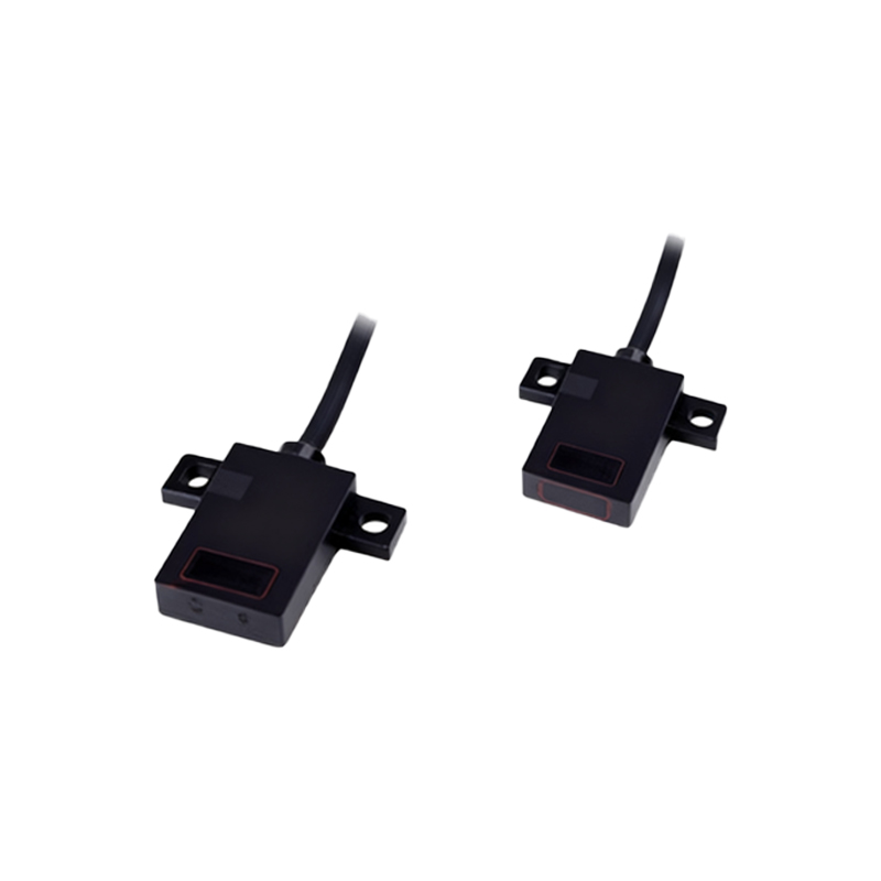
For electrical engineers, understanding the technical parameters is essential. The ITR sensor typically offers a detection range from a few millimeters to several meters, depending on the model. It operates on a voltage range of 5V to 24V DC, with a switching frequency up to 1 kHz. The output can be NPN or PNP, allowing compatibility with various PLCs and microcontrollers. Key features include immunity to ambient light interference, high repeatability, and a solid-state design that eliminates mechanical wear. The sensor also supports multiple sensing modes, such as through-beam, retro-reflective, and diffuse, each suited for specific applications. For example, through-beam mode provides the longest range and highest reliability, while diffuse mode is simpler to install.
Working Principle and Circuit Design
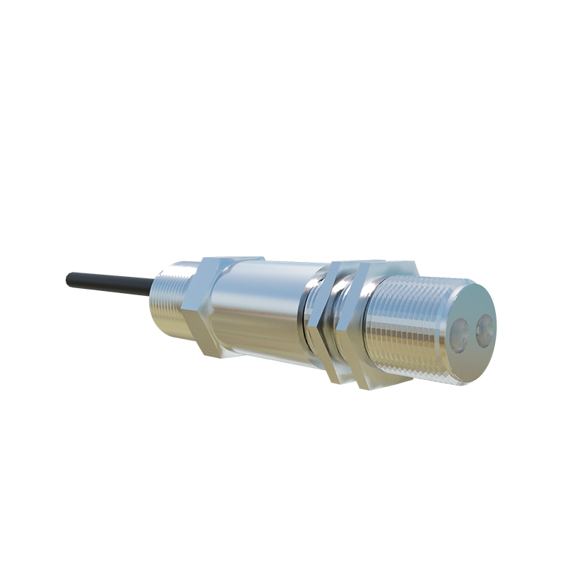
The ITR sensor operates based on the principle of light modulation. The emitter (LED) sends a pulsed infrared beam to a receiver (phototransistor or photodiode). When an object interrupts the beam, the receiver detects a change in light intensity, triggering a switching output. In circuit design, engineers must consider shielding against electromagnetic interference (EMI) and ensuring stable power supply decoupling. A typical circuit includes a phototransistor connected to a comparator to set the threshold. For enhanced performance, a modulation frequency of 10 kHz to 100 kHz is used to filter out ambient light. The output signal is then processed by a microcontroller or relay logic.
Installation Best Practices
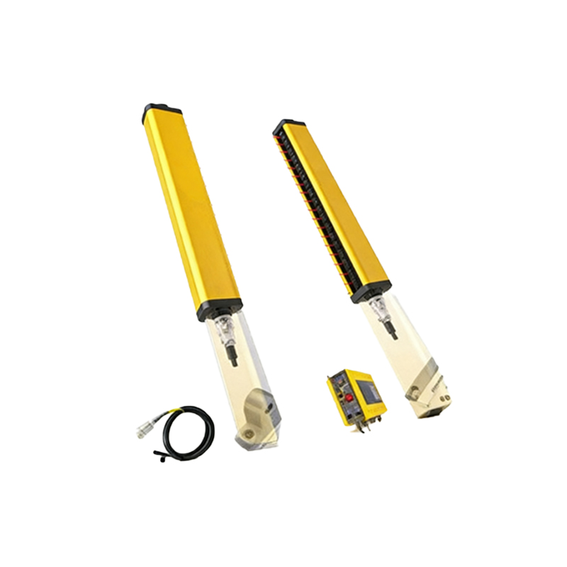
Proper installation is crucial for optimal performance. Engineers should mount the sensor on a stable surface to avoid vibration, which can cause false triggers. The sensing axis must be aligned precisely with the target object. For through-beam sensors, the emitter and receiver alignment is critical, often requiring laser-assisted setup. Wiring should follow shielded cables to minimize noise, with proper grounding at a single point. Additionally, the sensor's lens should be kept clean using a lint-free cloth and isopropyl alcohol, especially in dusty environments. Avoid exposure to direct sunlight or strong artificial lighting sources that could saturate the receiver.
Common Applications in Industrial Automation
In the industry, ITR sensors are employed in conveyor belt systems for detecting package presence, in packaging machines for counting items, and in safety systems for detecting machine guard openings. They are also used in elevators for door obstruction detection and in automotive assembly lines for part positioning. The sensor's ability to operate in high-temperature or wet conditions makes it suitable for food processing plants. For example, a diffuse ITR sensor can detect transparent bottles on a conveyor, while a retro-reflective sensor is ideal for detecting shiny metal parts without false reflections.
Diagnostics and Troubleshooting
Common issues include no output, false triggering, or reduced range. First, check the power supply voltage and wiring connections. Use a multimeter to verify the output transistor's switching action. For false triggering, inspect for reflective surfaces or dirt on the lens. Adjust the sensitivity potentiometer if available, or use a teach-in function on advanced models. If the range is reduced, confirm that the sensing distance matches the datasheet and that the target object's material (e.g., dark plastic vs. white metal) is appropriate. Recalibrate the sensor alignment for through-beam types.
Conclusion and Future Trends
The ITR series photoelectric sensor remains a staple in electrical engineering due to its simplicity and effectiveness. Future developments include integration with IoT for remote monitoring, higher resolution for precision detection, and energy-efficient designs using low-power LEDs. Engineers should stay updated with new models offering IO-Link communication for enhanced diagnostics. By mastering the ITR sensor's application, electrical professionals can significantly improve system reliability and productivity in automated environments.