Introduction to Photoelectric Sensors
Photoelectric sensors are essential components in industrial automation, enabling non-contact detection of objects, positions, and distances. These sensors use light beams to sense a target, making them ideal for environments where physical contact is impractical. As an electrical engineer, mastering their wiring principles ensures reliable system integration and minimizes troubleshooting time.
Key Wiring Components and Color Codes
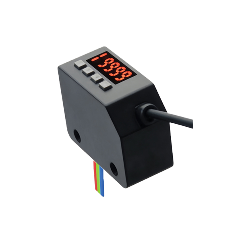
Standard photoelectric sensors feature three or four wires: power supply (typically brown for +V, blue for 0V), output signal (black for NPN, white for PNP in some models), and sometimes a shield wire for noise reduction. Always verify the manufacturer datasheet, as color codes vary. For three-wire sensors, the brown wire connects to the positive power terminal, blue to ground, and black to the PLC input. In four-wire systems, the white wire provides a complementary output.
Understanding NPN and PNP Output Configurations
NPN (sinking) outputs switch the load to ground when activated, while PNP (sourcing) outputs connect to the positive supply. For example, in a DC circuit with a PLC, an NPN sensor pulls the input low (0V), whereas a PNP sensor drives it high (+V). Choose based on your controller’s input type—most modern PLCs accept both, but older models may require a specific polarity. Miswiring can cause erratic behavior or damage.
Step-by-Step Wiring Process for a Typical Sensor
1. Power off the system and verify voltage compatibility (e.g., 10-30V DC).
2. Connect the brown wire to the positive terminal of the power supply.
3. Connect the blue wire to the negative terminal (ground).
4. For a PNP sensor, connect the black wire to the PLC input; for NPN, connect it to the load’s negative side.
5. Test with a multimeter: ensure voltage at the output pin changes from near 0V to the supply voltage when the sensor detects an object.
6. Secure all connections with proper insulation to prevent short circuits.
Common Wiring Mistakes and How to Avoid Them
One frequent error is reversing power wires, which may instantly destroy the sensor. Another is using the wrong output type—connecting a PNP sensor to an NPN-only input causes no signal. Also, ignoring cable shielding in high-EMI environments leads to false triggers. Use shielded twisted-pair cables and ground the shield at one end only. Finally, verify load current rating; exceeding it damages the output transistor.
Advanced Tips for Multi-Sensor Systems
When wiring multiple sensors to a single PLC, ensure each has a dedicated input or use multiplexing modules. Parallel wiring of outputs is not recommended as it can cause current hogging. For long cable runs (over 50m), consider using a sensor with a built-in amplifier or add a signal repeater. Always simulate the system with a test object before full deployment.
Conclusion and Best Practices
Mastering photoelectric sensor wiring involves understanding power supply polarity, output configurations, and environmental factors. Always document your wiring schema, label wires clearly, and perform a thorough check with a multimeter. This approach reduces downtime and enhances system reliability in industrial applications.