Understanding the Role of Reflector Tape in Photoelectric Sensors
Photoelectric sensors are essential in automation, material handling, and packaging industries. Reflector tape, or retroreflective tape, is a critical accessory for retroreflective photoelectric sensors. Unlike through-beam or diffuse sensors, retroreflective sensors require a reflector to bounce the emitted light back to the receiver. The tape is often used when a standard reflector is impractical due to space, vibration, or alignment constraints. As an engineer, selecting the correct tape ensures reliable detection, minimizing false triggers and downtime.
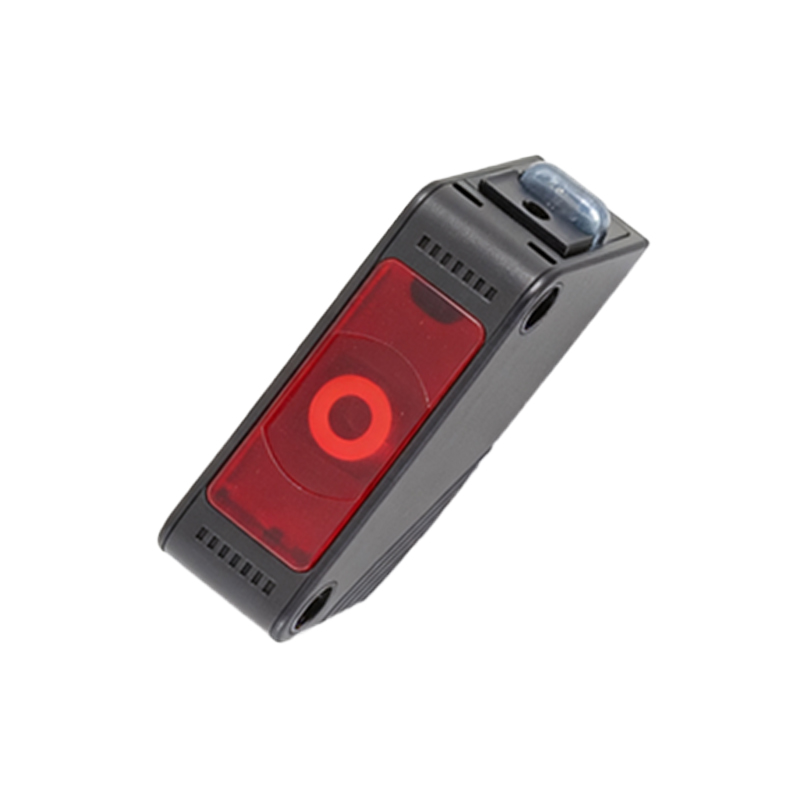
Selecting the Right Reflector Tape for Your Sensor
Not all reflector tapes are created equal. Key factors include the sensor’s wavelength (typically 660nm red or 880nm infrared), beam angle, and ambient conditions. For indoor applications with clean environments, standard polyester-based tape (e.g., 3M 8910 or similar) works well for distances up to 2-3 meters. For outdoor or dusty areas, use high-grade, weather-resistant tape with a prismatic micro-structure. Always match the tape’s reflectivity to the sensor’s sensing range—refer to the sensor datasheet for recommended tape types. Avoid using generic reflective materials, as they may scatter light, reducing detection accuracy.
Step-by-Step Installation Process
1. Clean the mounting surface: Use isopropyl alcohol to remove oil, dust, and moisture. A clean surface ensures strong adhesion and prevents tape peeling.
2. Cut the tape to the required size: Most retroreflective sensors work best with a tape area of at least 20x20 mm. For longer ranges (e.g., 10+ meters), use larger tape (e.g., 50x50 mm) to maintain signal strength.
3. Apply tape without air bubbles: Press firmly from center outward using a roller or squeegee. Air pockets degrade reflectivity.
4. Align the sensor head: Position the sensor perpendicular to the tape surface. Adjust tilt within ±5 degrees to maintain a clear optical path. For moving targets (e.g., conveyor belts), ensure the tape is stationary relative to the sensor beam.
Calibration and Testing After Installation
After mounting, power the sensor and verify its operation. Most sensors have an LED indicator for “stable on” or “light-on/dark-on” modes. Place an object between the sensor and tape—the output should change state. If detection is erratic, check for:
- Tape misalignment: Realign the sensor or tape.
- Distance exceedance: Confirm the tape’s reflectivity matches the sensor’s max range.
- Interference: Shield from ambient light or other sensors. Adjust the sensitivity potentiometer (if available) to fine-tune the threshold. Document the setup parameters for future maintenance.
Common Mistakes and Troubleshooting Tips
- Mistake 1: Using tape on curved surfaces. Solution: Use flexible tape or a curved reflector.
- Mistake 2: Overlapping tape strips. Solution: Use a single piece; overlapping creates dead zones.
- Mistake 3: Ignoring temperature ratings. Solution: Check tape specs—some fail above 85°C.
- Tip: Periodically inspect tape for wear, especially in high-vibration areas. Replace if reflectivity drops below 80% of original value (measure with a reflectometer if available).
Best Practices for Long-Term Reliability
- Apply tape to shielded backing (e.g., metal plate) if the surface is rough or painted.
- Use protective covers in abrasive environments (e.g., particle blasting).
- Schedule regular cleaning with a soft cloth and water—avoid solvents that degrade tape adhesive.
- In multi-sensor arrays, space tapes at least twice the beam width apart to avoid crosstalk.
- Document tape part numbers and installation dates in your maintenance log for traceability.