Understanding the Sensor and the Break
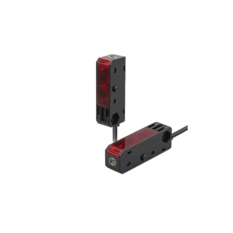
As an electrical engineer in the automation field, you often face the challenge of a broken photoelectric sensor wire. The first step is to identify the type of sensor. Most photoelectric sensors use three wires: brown for power (typically 10-30 VDC), blue for ground (0 V), and black for output (NPN or PNP). A broken wire can occur at the sensor head, along the cable, or at the connector. Always power down the system before inspection to avoid short circuits or personal injury. Use a multimeter to confirm the location of the break by checking continuity between the suspected section and the sensor’s internal circuit. If the break is near the sensor housing, you may need to replace the entire unit, but if it’s along the cable, you can proceed with a splice.
Tools and Materials Required
For a reliable repair, gather the following: a wire stripper (adjustable to 20-24 AWG), a soldering iron with lead-free solder, heat shrink tubing (matching the cable diameter), a multimeter, and electrical tape for temporary insulation. In harsh industrial environments, consider using a waterproof splice kit or a crimp connector with a sealant. Avoid using twist-and-tape methods, as they degrade over time due to vibration and moisture. For long-term durability, solder the connection and cover it with dual-layer heat shrink (adhesive-lined) to create a moisture-proof seal. If the sensor is part of a safety circuit, adhere to ISO 13849 standards by using a factory-repaired cable or a certified replacement.
Step-by-Step Reconnection Process
First, cut the cable at the break point, ensuring clean ends. Strip about 5 mm of insulation from each wire end. For a three-wire sensor, match the colors: brown to brown, blue to blue, and black to black. If the sensor uses a shielded cable (e.g., for noise reduction), connect the drain wire (bare or green) to the ground at one end only to avoid ground loops. Slide a section of heat shrink tubing over each wire before soldering. Tin the wire ends with solder, then join them; apply heat to melt the solder and shrink the tubing. For each wire, ensure the tubing covers the exposed metal completely. After all wires are joined, bundle them and apply a larger heat shrink tube over the entire splice for mechanical protection. Finally, use a multimeter in continuity mode to verify no short circuits between wires (e.g., from brown to black). Power up the system and test the sensor by blocking its beam; the output should toggle as expected.
Testing and Troubleshooting Tips
After reconnection, perform a functional test. If the sensor fails to operate, check the power supply voltage at the brown wire relative to blue; it should be within the sensor’s rated range (e.g., 24 VDC ±10%). For output testing, connect a load resistor (e.g., 1 kOhm) between the black wire and the power supply (for NPN, to blue; for PNP, to brown). If the output remains high or low regardless of the beam state, the sensor’s internal electronics might be damaged from the break-induced short. In such cases, replace the sensor. Common mistakes include reversing wires (e.g., swapping brown and black), which can damage the sensor, or using insufficient heat shrink, leading to corrosion. Always document the repair in your maintenance log, noting the cable length and environmental conditions (e.g., temperature, chemical exposure) to prevent future failures.
Preventive Measures for Future Reliability
To minimize the risk of cable breaks, use strain reliefs at sensor mounting points and route cables away from moving parts. For high-vibration applications, specify sensors with armored cables or metal conduit. Consider wireless photoelectric sensors for hard-to-reach areas, though they require battery or energy harvesting. Regularly inspect cables for cuts or abrasions during preventive maintenance; replace damaged sections before they break. In corrosive environments, apply a dielectric grease to connectors. By following these best practices, you can extend the lifespan of your sensor installations and reduce downtime. Remember, a proper repair not only restores functionality but also maintains safety and signal integrity.