Understanding the Photoelectric Sensor and PLC Interface
In industrial automation, photoelectric sensors are widely used for object detection, counting, and positioning. They emit a beam of light (infrared, visible, or laser) and detect changes in the received light intensity. To integrate them with a PLC, the first step is to understand the sensor’s output type. Most photoelectric sensors offer either NPN (sinking) or PNP (sourcing) outputs, which determine how the signal connects to the PLC input module. For example, a standard three-wire sensor includes a brown wire for +24V DC, a blue wire for 0V DC, and a black wire for the output signal. Ensure your PLC input module supports the same voltage level, typically 24V DC for industrial systems.
Selecting the Correct PLC Input Module
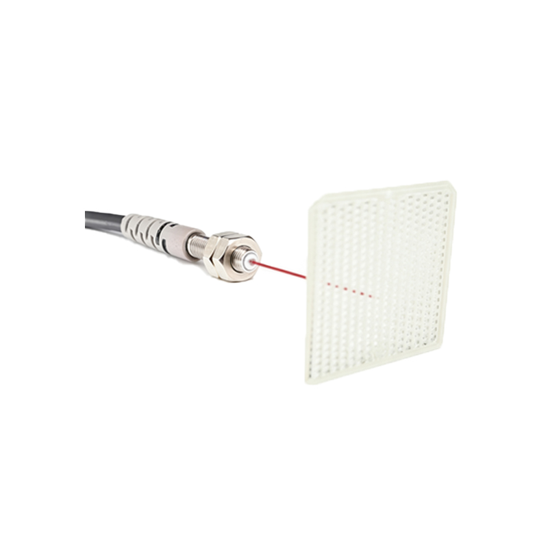
Before wiring, match the sensor output type to the PLC input module. For PNP sensors, the output signal goes high (supplies voltage) when active, so connect it to a sourcing input module or a sinking input with a pull-down resistor. For NPN sensors, the output goes low (sinks to ground) when active, requiring a sinking input module or a sourcing input with a pull-up resistor. Most modern PLCs, such as Siemens S7-1200 or Allen-Bradley CompactLogix, have configurable input modules that can handle both types with appropriate wiring. Always check the PLC manual for the specific input module model to avoid short circuits or damage.
Wiring the Sensor to the PLC Input
For a typical PNP sensor connection, connect the brown wire to the PLC’s +24V DC power supply, the blue wire to the 0V DC common ground, and the black wire to the PLC digital input terminal (e.g., I0.0). For an NPN sensor, the brown wire goes to +24V DC, blue to 0V DC, and black to the PLC input terminal. However, ensure the PLC input common terminal is connected to 0V DC for PNP sensors or to +24V DC for NPN sensors to complete the circuit. Use shielded twisted-pair cables for long distances to reduce electrical noise, and ground the shield at one end only to prevent ground loops.
Configuring the PLC Program for Sensor Input
After hardware wiring, configure the PLC software to read the sensor signal. For example, in TIA Portal for Siemens PLCs, assign the input address (e.g., I0.0) to a digital input tag. Write a simple ladder logic rung: when the input is true (sensor detects object), set an output (e.g., Q0.0) to activate a conveyor motor or increment a counter. For high-speed applications like fast-moving objects, consider using a high-speed counter (HSC) module if the sensor’s response time is below 1 ms. Additionally, set debounce filters in the PLC to ignore short noise spikes, typically 10-50 ms.
Troubleshooting Common Connection Issues
If the sensor does not respond, first check the power supply voltage and polarity using a multimeter. Verify that the sensor’s LED indicator lights up when an object is detected. If the PLC input LED does not turn on, test the wiring by temporarily connecting the output wire directly to the PLC common terminal (for PNP, connect to 0V; for NPN, connect to +24V) to see if the input triggers. If the signal is intermittent, inspect for loose connections or excessive cable length (over 100 meters may require a signal booster). Also, ensure the sensor’s detection range and sensitivity are set correctly for the object material and color.
Advanced Integration with Analog Sensors
Some photoelectric sensors provide analog outputs (e.g., 0-10V or 4-20 mA) for distance or intensity measurement. For these, use a PLC analog input module instead of digital inputs. Wire the analog output to the analog input terminal (e.g., AI0), and configure the module’s scaling in the PLC software (e.g., raw value to millimeters). For 4-20 mA current loops, ensure the PLC module’s internal resistor (typically 250 ohms) is present or add an external resistor. This setup enables precise object position or color detection in complex processes.