Proximity sensors are fundamental components in modern automation, robotics, and safety systems. Their primary function is to detect the presence or absence of an object without physical contact. While the sensing technology—be it inductive, capacitive, photoelectric, or ultrasonic—often takes center stage, the electrical parameter that truly enables their operation is voltage. Understanding proximity sensor voltage is not merely a technical detail; it is critical for ensuring reliable performance, system compatibility, and operational safety. This guide delves into the essential aspects of voltage as it pertains to these ubiquitous devices.
At its core, the voltage specification for a proximity sensor defines the electrical potential required to power its internal circuitry. This includes the oscillator, amplifier, and output switching components. Most industrial proximity sensors are designed to operate on Direct Current (DC) voltage, with common nominal values being 10-30V DC or 12-24V DC. This range is specified to account for real-world fluctuations in power supplies. A sensor rated for 10-30V DC will function correctly as long as the supplied voltage stays within these boundaries. Operating a sensor below its minimum voltage can lead to failure to switch on or erratic detection behavior. Conversely, applying voltage above the maximum rating can cause permanent damage to the internal electronics, typically by overheating or component failure.
Alternating Current (AC) powered proximity sensors also exist, often found in older installations or specific high-power applications, with common ratings like 90-250V AC. It is paramount never to confuse AC and DC voltage requirements. Connecting a DC sensor to an AC supply, or vice versa, will almost certainly result in immediate and catastrophic failure. The sensor's datasheet and housing are always clearly marked with the voltage type and range.
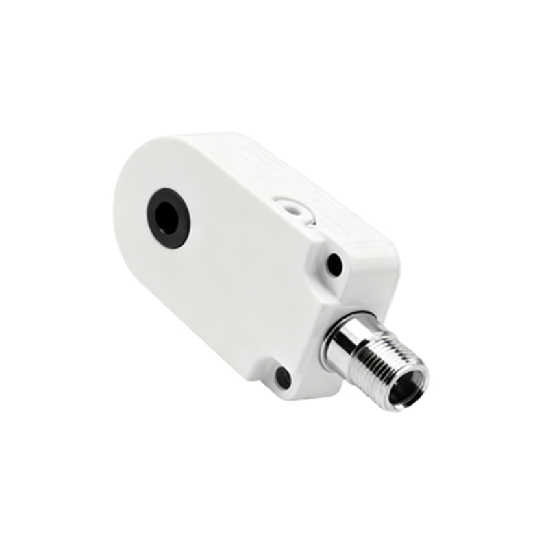
The operating voltage directly influences the sensor's output characteristics. In a 3-wire DC sensor, the output switch (typically an NPN or PNP transistor) is powered by the same supply. The voltage present at the output wire when active (the "load voltage") will be very close to the supply voltage, minus a small internal drop. This means a sensor powered by 24V DC will switch a 24V load. Ensuring compatibility between the sensor's output voltage and the input voltage requirement of the connected device—such as a Programmable Logic Controller (PLC) input, relay, or indicator lamp—is essential. A mismatch here is a common source of system malfunction.
Beyond nominal operation, several voltage-related concepts are crucial for robust system design. First is the concept of voltage drop. In long wire runs, resistance in the cables can cause a significant reduction in voltage between the power supply and the sensor. A sensor at the end of a 100-meter cable might receive only 20V from a 24V supply, which must still be above its minimum operating threshold. Using appropriately sized cables is vital.
Second is protection against voltage spikes and transients. Industrial environments are electrically noisy. Sudden spikes from inductive loads (like motors or solenoids) switching off can travel back through the wiring and damage sensitive sensor electronics. Many sensors incorporate built-in protection circuits, such as surge suppressors, but additional external protection modules are often recommended for longevity.
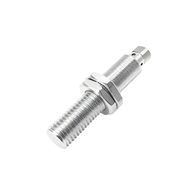
Third is the distinction between operating voltage and switching capacity. While a sensor might operate on 24V, its solid-state output may only be rated to switch a maximum current (e.g., 200mA). Connecting a load that draws more current can destroy the output transistor. Always check the maximum load current specification alongside the voltage rating.
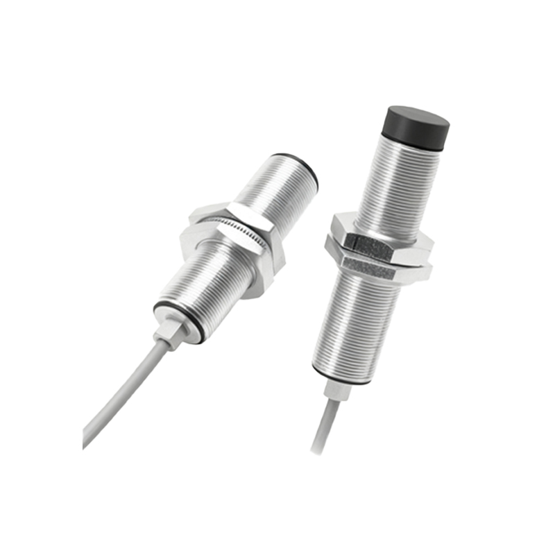
For system integrators, managing proximity sensor voltage involves a few key practices. Always begin by consulting the manufacturer's datasheet for the exact voltage range, type (AC/DC), and connection diagram. Use a stable, regulated power supply that matches the sensor's requirements and is capable of supplying the necessary current for all connected sensors. Implement proper wiring techniques: use shielded cables in electrically noisy environments, keep sensor wires away from high-power cables, and ensure all connections are tight and corrosion-free. Finally, consider using protective devices like fuses, circuit breakers, or transient voltage suppression diodes on the supply line to safeguard the sensor from external electrical faults.
In summary, voltage is the lifeblood of a proximity sensor. A deep understanding of its operating range, its impact on output signals, and the strategies to manage it in a real-world electrical environment is indispensable. By paying close attention to these voltage parameters—selecting the correct power supply, ensuring compatibility with connected loads, and protecting against electrical hazards—engineers and technicians can guarantee that their proximity sensing systems perform reliably, accurately, and safely for years to come. Ignoring these fundamentals often leads to intermittent failures, costly downtime, and premature device replacement.