1. Light Emitter (Transmitter)
The core of any photoelectric sensor system begins with the light emitter, typically a solid-state LED or laser diode. This component generates a focused beam of light, which can be visible red, infrared, or ultraviolet depending on the application. In industrial environments, the emitter’s wavelength and intensity are critical for detecting objects with varying surface reflectivity, color, or transparency. Engineers must consider factors like ambient light interference and beam divergence when selecting the emitter, as these directly affect sensing range and accuracy in harsh manufacturing settings.
2. Light Receiver (Photodetector)
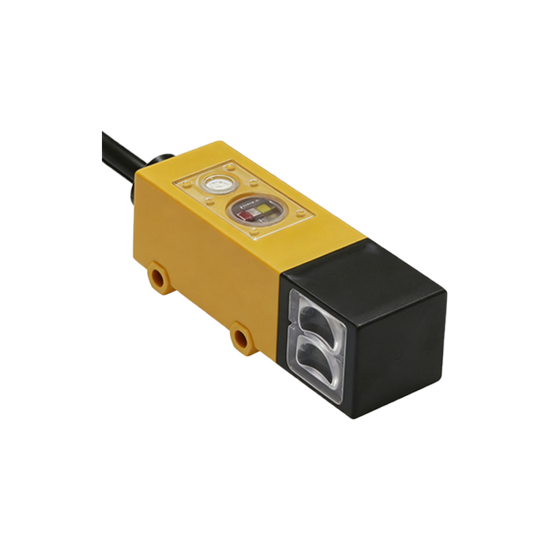
The receiver, often a photodiode, phototransistor, or photoelectric integrated circuit, converts the received light signal into an electrical current. This component is responsible for distinguishing between the presence and absence of the light beam. Advanced receivers include sensitivity adjustments and signal amplification modules to filter out noise from factory lighting or dust. For long-range or high-speed applications, avalanche photodiodes are preferred due to their rapid response times and high gain.
3. Optics and Lens System
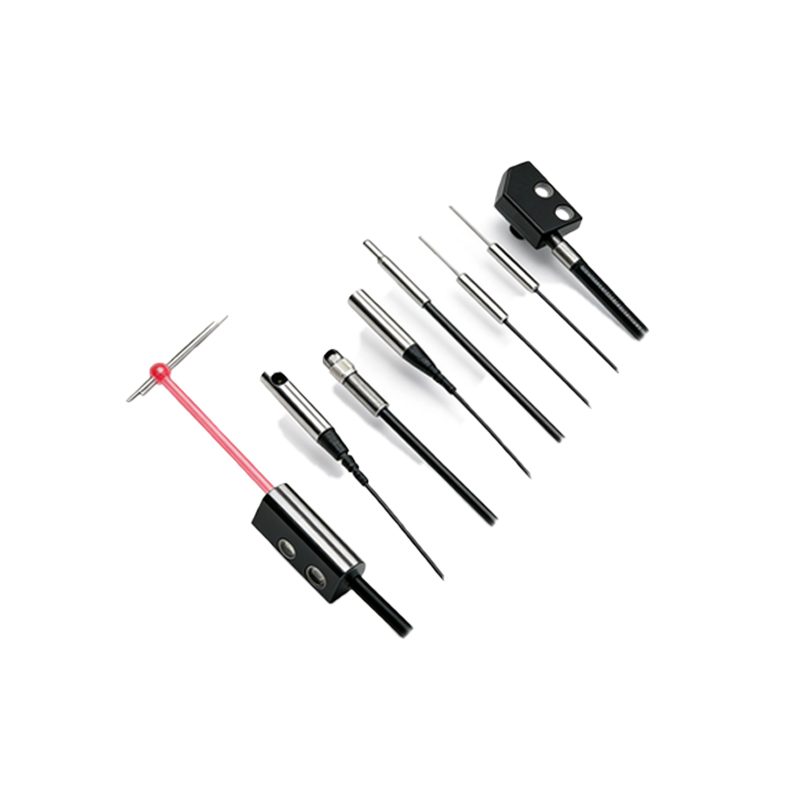
The optical assembly—comprising lenses, mirrors, and fiber optic cables—shapes and directs the light beam. Converging lenses focus the beam into a narrow path for precision detection, while diffusing lenses spread light for wide-area coverage. Anti-reflective coatings are essential to minimize light loss and false triggers. In through-beam systems, alignment lenses ensure the emitter and receiver remain precisely configured, even under vibration or thermal expansion.
4. Electronic Control Circuitry
This module processes the receiver’s output and triggers the sensor’s switching action. It includes a comparator circuit that compares the signal level to a pre-set threshold, a timer for delay adjustments, and an output driver (e.g., NPN, PNP, or push-pull). Modern systems incorporate microcontrollers for auto-calibration, background suppression, and diagnostic feedback. Engineers must evaluate circuit noise immunity and power supply stability to prevent malfunction in electrically noisy environments like motor drive cabinets.
5. Housing and Environmental Protection
The physical enclosure protects internal components from moisture, dust, chemicals, and mechanical impact. Common materials include die-cast zinc, stainless steel, and high-impact plastic, with IP67 or IP69K ratings for washdown applications. The housing design often includes mounting brackets, cable glands, and status indicator LEDs. For high-temperature environments, heat-dissipating coatings or active cooling may be integrated.
6. Output Interface and Connectivity
The final component is the output interface, which transmits the detection signal to a PLC, relay, or safety controller. Options include discrete wiring (e.g., M12 connectors), IO-Link communication, or fieldbus protocols like PROFINET and EtherNet/IP. Engineers must ensure the output type matches the controller input requirements and that cable lengths do not exceed voltage drop limitations. Redundant outputs are common in safety-critical systems for fail-safe operation.