Understanding the Tripping Phenomenon
In industrial automation, photoelectric sensors are critical components for object detection, positioning, and counting. A common yet hazardous practice observed in some facilities is the replacement or adjustment of these sensors while the control circuit remains energized. This action often leads to unexpected tripping of circuit breakers, motor protection devices, or even the entire machine safety system. The tripping is not a random failure but a direct consequence of violating fundamental electrical safety and operational principles. When a sensor is disconnected under load, it can create an open circuit in a control loop or cause a sudden change in current flow. Many modern programmable logic controllers (PLCs) and safety relays monitor the integrity of sensor circuits. An abrupt disconnection can be interpreted as a wire break or a fault condition, triggering a safety shutdown to prevent potential damage or hazardous machine operation. Furthermore, the inductive nature of connected loads like solenoids or relay coils can generate voltage spikes when the circuit is interrupted, potentially leading to nuisance trips or even damage to sensitive electronics.
Electrical and Safety Mechanisms Behind the Trip
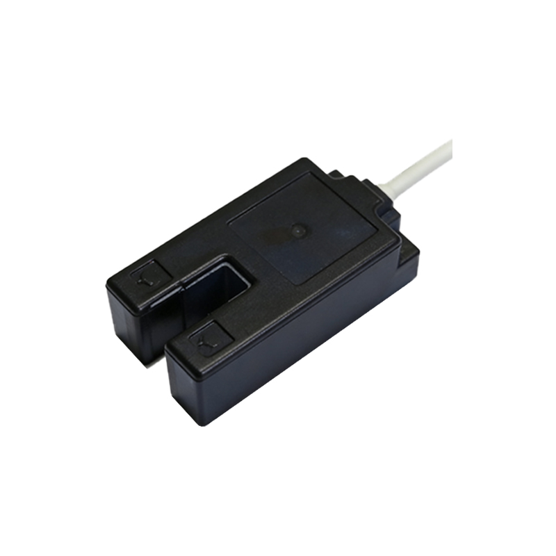
The core reason for tripping lies in the design of control and safety circuits. Most industrial control systems operate on low-voltage DC circuits (e.g., 24VDC) for sensors. These circuits are often protected by electronic circuit breakers or fuses with very fast response times. When a live connector is pulled, even for a fraction of a second, it can cause a brief but significant arc or a sudden drop in current. Solid-state output modules in PLCs and DC switching power supplies are designed to detect such anomalies. For instance, a power supply with short-circuit protection might see the initial spark of connection/disconnection as a fault and momentarily shut down its output, causing a voltage dip that resets controllers. In three-wire DC sensors, disconnecting the brown (live) or blue (neutral) wire under power can create a short through the housing or the user's tools if not done perfectly, directly causing a short-circuit trip. For AC sensors, the risks are higher due to the potential for phase-to-phase or phase-to-ground faults. Safety circuits, particularly those designed to Category 3 or 4 per ISO 13849, use monitored inputs. Any unexpected change in the signal state, such as a sensor going from "on" to "off" without a corresponding machine state change, is flagged as an error, leading to a controlled stop or an emergency shutdown.
Risks Beyond Tripping: Equipment and Personnel Hazards
Focusing solely on the tripping event underestimates the severe risks involved. The primary danger is electrical shock to the technician. Sensor housings are typically metallic or have conductive parts. If a tool slips or a finger touches a live terminal during the hot-swap process, it can result in serious injury, especially with higher voltage AC sensors. Arcing can cause burns and is a potential ignition source in environments with flammable dust or vapors. From an equipment perspective, voltage transients (spikes) generated during disconnection can travel back through the wiring and damage other connected devices, such as the PLC input module, the sensor's own internal electronics, or nearby communication modules. These spikes degrade insulation over time, leading to premature failure. The tripping itself causes unplanned downtime, disrupting production schedules. Repeated trips from such practices can also desensitize maintenance personnel to alarm conditions, creating a "cry wolf" scenario where a genuine critical fault might be ignored, leading to major equipment damage or safety incidents.
Correct Procedures for Safe Sensor Replacement
The only safe and correct procedure is to perform sensor replacement with the control circuit completely de-energized and locked out following a proper Lockout/Tagout (LOTO) protocol. First, identify the correct circuit breaker or fuse supplying power to the sensor and the associated controller. Use the electrical drawings. Second, safely disconnect and lock out the power source. Verify the absence of voltage at the sensor terminals using a properly rated voltage tester. Only then should the faulty sensor be disconnected. Before installing the new sensor, verify its specifications (voltage, output type NPN/PNP, NO/NC) match the old one and the system requirements. Ensure the wiring is correct and terminals are tightened to the specified torque. After installation, remove lockout devices, restore power, and perform a functional test by actuating the sensor. For systems where downtime is critical, design engineers should consider using plug-and-play sensor modules with quick-disconnect connectors that are designed to be disconnected under specific low-energy conditions, or implement redundant sensing schemes that allow one sensor to be taken offline safely.
Engineering Solutions to Minimize Downtime
To eliminate the temptation and need for live work, engineers can incorporate several design features. Using sensors with built-in diagnostics and quick-change capabilities can reduce replacement time. Implementing local disconnect switches or circuit breakers specifically for sensor clusters allows isolation of a small section without shutting down the entire line. Designing control logic with a "maintenance mode" can help. In this mode, the PLC can be programmed to ignore faults from a specific sensor group for a limited time, allowing for safe replacement while other machine functions remain active, though power isolation at the sensor itself remains mandatory. Another solution is the use of relay or contactor-isolated sensor circuits. A maintenance person can de-energize a dedicated relay that cuts power to a bank of sensors, enabling safe exchange. For highly critical processes, redundant sensor systems (e.g., two sensors in a voting logic) allow one to fail or be replaced without stopping the process. Ultimately, fostering a strong safety culture with regular training on electrical hazards and strict enforcement of LOTO procedures is the most effective engineering and administrative control to prevent incidents related to live sensor replacement.