Introduction to Photoelectric Sensor Symbols
In the realm of industrial automation and electrical engineering, photoelectric sensors are indispensable components for detecting the presence, absence, or distance of objects without physical contact. Their operation is based on the transmission and reception of light, typically from an LED source. To effectively design, troubleshoot, and interpret complex control systems, engineers and technicians must be fluent in the symbolic language of electrical schematics. These symbols provide a universal shorthand, conveying the sensor's function, type, and electrical connections at a glance. Understanding these symbols is not merely an academic exercise; it is a fundamental skill for integrating these devices into programmable logic controller (PLC) systems, safety circuits, and intricate machinery. This article delves into the common symbols used for photoelectric sensors, explaining their components and variations found in standard schematic diagrams.
Core Components and Basic Symbol Structure
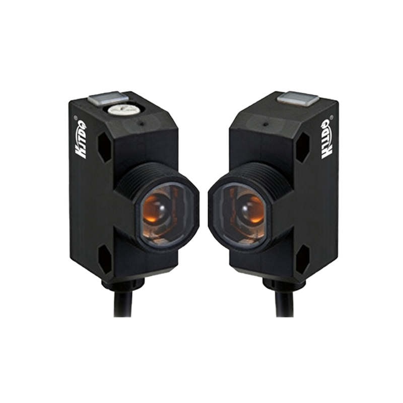
The fundamental symbol for a photoelectric sensor in an electrical schematic is not a single icon but a combination of elements representing its internal components. At its heart, the symbol is divided into two primary parts: the emitter (light source) and the receiver (photodetector). The emitter is universally represented by a diode symbol—a triangle pointing towards a vertical line—often with two arrows pointing outward to indicate light emission. This symbol is typically labeled with the type of light, such as "IR" for infrared. The receiver is commonly depicted as a photodiode or phototransistor symbol, which resembles a standard diode or transistor but is enclosed in a circle with inward-pointing arrows to signify light reception. These two components are usually shown separately on the schematic, connected by dashed lines or a "light beam" line to indicate the non-physical, optical link between them. The power supply terminals, output switching element (usually an NPN or PNP transistor), and ground connections are also integral parts of the complete symbol.
Symbol Variations for Different Sensing Modes
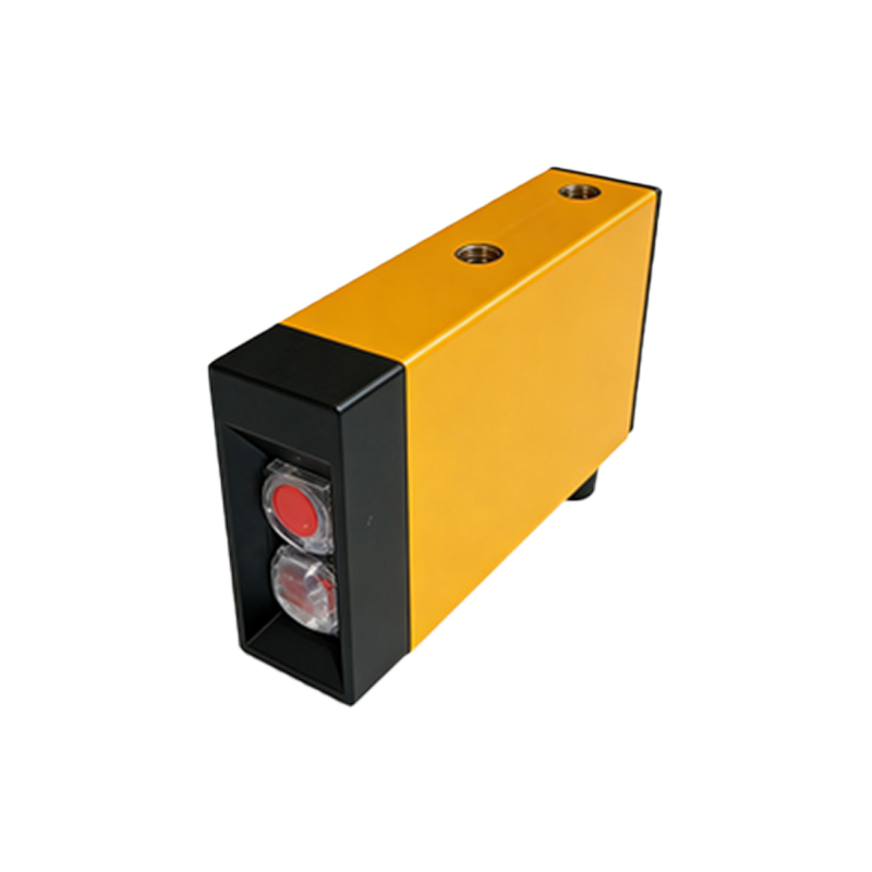
The schematic symbol adapts to represent the three primary operating modes: through-beam, retro-reflective, and diffuse (proximity). For a through-beam sensor, the symbols for the emitter and receiver are placed opposite each other, clearly separated, with the light beam line connecting them. This visually indicates that the object to be detected breaks the beam between two distinct units. A retro-reflective sensor uses a combined symbol where the emitter and receiver are housed in a single unit. The symbol often shows both components side-by-side within one enclosure, with the light beam line extending out and returning via a zigzag or looped line, representing reflection from a dedicated reflector. Diffuse sensors, which detect light reflected directly from the target object, are symbolized with the emitter and receiver in one housing, and the light beam line simply projecting out and ending, implying the reflection path is not fixed.
Interpreting Output Configuration Symbols
A critical aspect of the photoelectric sensor symbol is its output configuration, which defines how it interfaces with the control circuit. This is represented by the internal switch symbol connected to the receiver. The two main types are NPN (sinking) and PNP (sourcing) outputs. An NPN output symbol will show the switching transistor with the emitter connected to the common negative (0V). In contrast, a PNP output symbol shows the transistor with the emitter connected to the positive supply voltage. The output line is usually labeled "OUT" or "LOAD." Furthermore, the symbol indicates the output's normal state: normally open (NO) or normally closed (NC). A break in the switch line represents NO (closes upon detection), while a connected switch line represents NC (opens upon detection). These details are paramount for correctly wiring the sensor to a PLC input module or a relay to ensure proper logic operation.
Additional Annotations and Practical Considerations
Beyond the core graphical elements, schematic symbols include essential alphanumeric annotations. These include the sensor's reference designator, such as "PE1" or "BGS" (for Background Suppression sensor). Voltage ratings (e.g., 10-30 VDC), timing diagrams for on-delay/off-delay functions, and connection pin numbers (1:+, 2:-, 3:OUT) are often noted nearby. Understanding these symbols allows for efficient system design, enabling engineers to plan cable runs, power supplies, and interfacing correctly. During troubleshooting, a quick glance at the schematic can reveal if a sensor is wired in a sourcing or sinking configuration relative to the PLC, a common source of installation errors. Mastery of this symbolic language ensures clear communication across technical documents, from initial system diagrams to maintenance manuals, and is essential for anyone working with modern automated electrical systems.