Understanding the Fundamentals of Photoelectric Sensor Symbols
Photoelectric sensor symbols are the standardized graphical language used in electrical schematics, ladder diagrams, and technical documentation to represent these ubiquitous industrial components. At their core, these symbols convey the sensor's type, function, and electrical connection points without requiring a detailed drawing of the physical device. The basic symbol typically resembles a rectangle or a circle with specific internal markings and external connection lines. The rectangle often represents the sensor's housing or amplifier unit, while the circle might denote the optical head or emitter/receiver pair. Mastery of these symbols is not merely an academic exercise; it is a critical skill for engineers and technicians involved in designing, installing, troubleshooting, and maintaining automated systems. Accurate interpretation ensures correct wiring, proper system integration, and efficient diagnostics, preventing costly downtime and errors in complex control panels and machinery layouts.
Decoding the Core Symbol Components
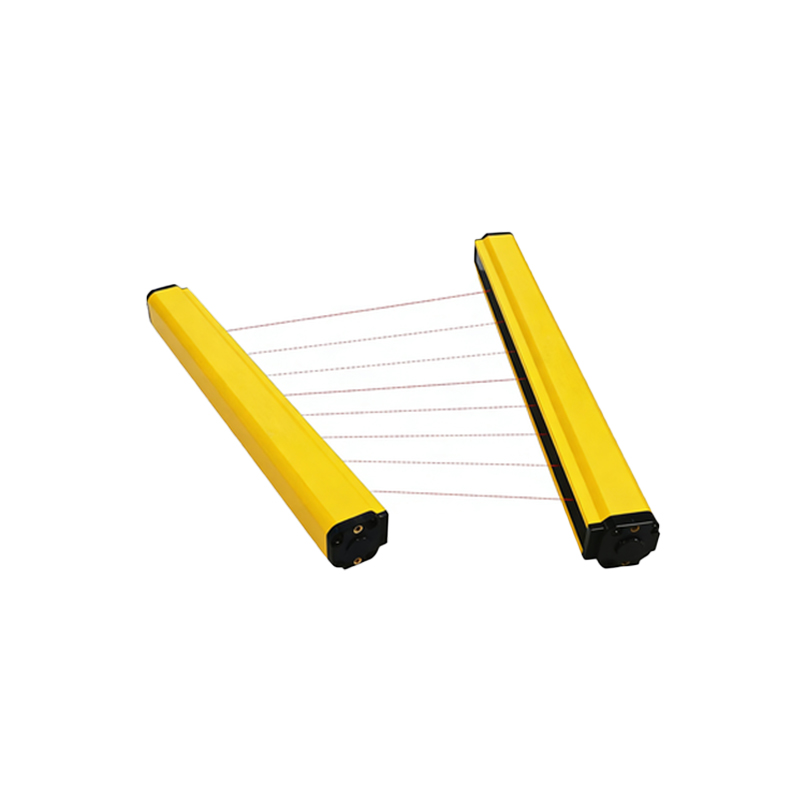
The primary symbol components are the emitter and the receiver. The emitter, or light source, is commonly represented by a diode symbol (a triangle pointing to a line) with arrows pointing outward, indicating light emission. This is often labeled as "LED" or simply "E". The receiver, which detects the light, is usually shown as a phototransistor or photodiode symbol (a diode symbol with arrows pointing inward) and may be labeled "R" or "PT". In a through-beam sensor symbol, these two elements are depicted as separate symbols, connected by a dashed or dotted line representing the light beam. For a retro-reflective sensor, both emitter and receiver are shown within a single housing symbol, with the light beam path indicated as a line bouncing off a stylized reflector. Diffuse (proximity) sensors combine the emitter and receiver in one symbol, with the light beam shown reflecting off a generic target. The power supply connections, typically for DC sensors, are marked as +V (or 24V) and 0V (or COM). The output signal line, which is the critical interface to the PLC or controller, is clearly indicated, often with the load (like a relay coil or PLC input) shown connected to it.
Interpreting Output Types: NPN vs. PNP and NO vs. NC
One of the most crucial aspects of a photoelectric sensor symbol is its output configuration. This is defined by two key characteristics: the transistor type (sourcing or sinking) and the switching state. The symbol explicitly indicates whether the output is NPN (sinking) or PNP (sourcing). In an NPN sensor symbol, the output transistor's emitter is connected to the 0V line. In a PNP symbol, the transistor's emitter is connected to the +V line. This determines how the sensor must be wired to the load. Equally important is the switching logic: Normally Open (NO) or Normally Closed (NC). In a NO symbol, the output switch is shown as open when the sensor is not activated (no target detected). Upon detection, the switch closes, completing the circuit. For a NC symbol, the switch is shown as closed in the idle state and opens upon detection. The symbol uses the standard open/closed switch representation within the rectangle, often adjacent to the output line. Misreading this can lead to a control system behaving in the exact opposite of the intended manner.
Analyzing Special Function Indicators and Markings
Beyond the basic emitter, receiver, and output, symbols incorporate additional markings to denote special functions. A timer function, for example, might be represented by a small clock icon or the letters "TON" (Timer On-Delay) or "TOF" (Timer Off-Delay) inside the symbol rectangle. Sensors with a teach-in or programmable function may show a small "P" or a hand icon. The symbol for a background suppression sensor might include a curved line or a specific notation like "BGS". Light-on/Dark-on operation is another critical parameter. A "Light-on" sensor (output activates when light is received) might have a small sun icon, while a "Dark-on" sensor (output activates when light is blocked) could have a darkened circle. Analog output sensors are denoted by a wavy line next to the output, representing the analog signal. Push-pull or complementary outputs (both NO and NC available simultaneously) are shown with two separate switch symbols. These markings are essential for selecting the correct sensor for advanced applications like edge detection, precise positioning, or contrast recognition.
Practical Application in Circuit Diagrams and Troubleshooting
In a full circuit diagram or ladder logic, the photoelectric sensor symbol is not isolated. It is connected to a power source and a load, such as a PLC input module. Reading the symbol in context involves tracing these connections. For instance, a PNP NO sensor's output line should connect to the PLC's sinking input card. If the symbol shows an NPN sensor but the wiring diagram connects it to a sourcing input, a mismatch is immediately apparent. During troubleshooting, the symbol provides a roadmap. By understanding the symbol, a technician knows which terminals to probe for voltage. If a diffuse sensor with a relay output (indicated by a standard relay coil symbol inside the rectangle) is failing, the technician checks first for power at the supply terminals, then for the presence of the output signal at the switch contacts when a target is presented. Cross-referencing the symbol on the schematic with the manufacturer's datasheet, which provides the exact terminal layout (e.g., brown wire to +V, blue to 0V, black to output), is the final step in practical application, bridging the gap between abstract symbolism and physical implementation.