Introduction to Photoelectric Sensor Voltage Measurement
Accurate voltage measurement is a cornerstone of ensuring the reliability and performance of photoelectric sensors in industrial automation. These sensors, which detect the presence, absence, or distance of an object using a light transmitter and receiver, rely on stable and precise electrical power. Voltage serves as the fundamental parameter that dictates the sensor's operational integrity, output signal stability, and overall longevity. Fluctuations or inaccuracies in the supplied voltage can lead to false triggering, reduced sensing range, or complete sensor failure, resulting in costly downtime. Therefore, understanding the principles and methodologies for proper voltage measurement is not merely a technical detail but a critical maintenance and troubleshooting skill for engineers and technicians working with automated systems.
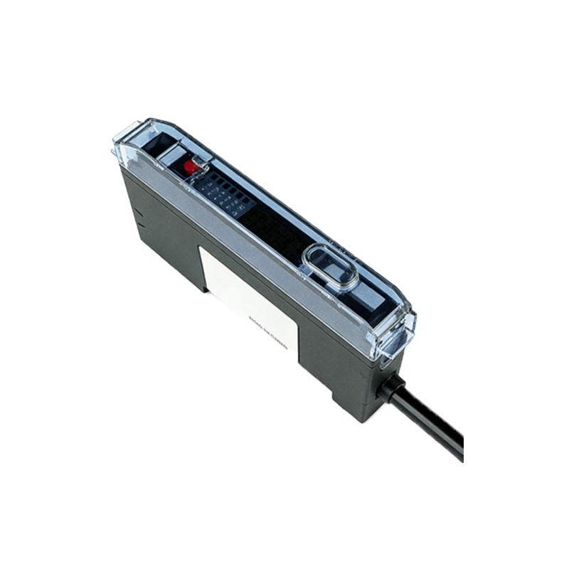
Understanding Sensor Power Requirements
Before any measurement is taken, it is imperative to consult the sensor's datasheet for its specific voltage requirements. Most industrial photoelectric sensors operate on Direct Current (DC) voltages, with common ranges being 10-30 VDC or 12-24 VDC. Some models may also operate on Alternating Current (AC), such as 90-250 VAC. The datasheet will specify the nominal operating voltage (e.g., 24 VDC), the allowable voltage range (e.g., 10-30 VDC), and the ripple tolerance. Operating a sensor outside its specified range can permanently damage its internal circuitry. Furthermore, the datasheet will indicate the sensor's current consumption, which is vital for properly sizing the power supply. A power supply with insufficient current capacity will cause a voltage drop under load, leading to unreliable sensor operation even if the no-load voltage measurement appears correct.
Essential Tools for Voltage Measurement
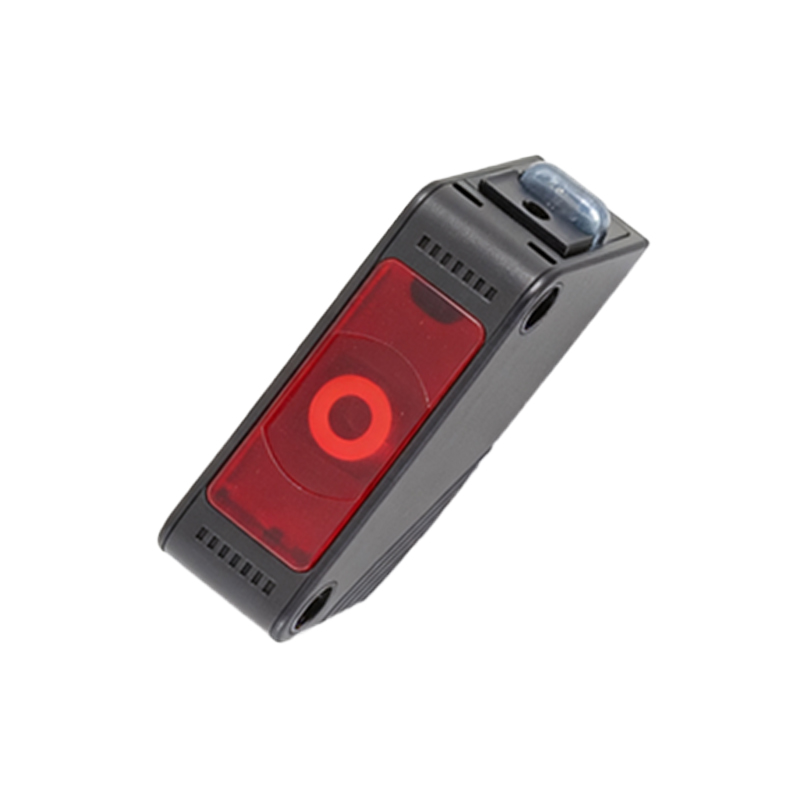
The primary tool for this task is a digital multimeter (DMM) with appropriate accuracy and safety ratings for industrial environments. For DC voltage measurements, a standard handheld DMM with a basic accuracy of ±0.5% or better is typically sufficient. Key features to look for include True RMS measurement capability (crucial if measuring AC sensors or noisy power lines), high input impedance (to minimize circuit loading), and robust safety certifications (like CAT III or CAT IV for measurements on industrial distribution systems). High-quality test leads with insulated probes and alligator clips are essential for making secure connections. For advanced diagnostics, an oscilloscope can be invaluable for visualizing voltage ripple, noise, or transient spikes that a DMM might average out, as these can significantly impact sensor performance.
Step-by-Step Measurement Procedure
First, ensure the sensor circuit is powered and in its normal operating state. Set the multimeter to the correct function (VDC or VAC) and a range higher than the expected voltage. For a 24 VDC system, select the 200 VDC or auto-ranging setting. Identify the sensor's power terminals, typically labeled as V+ (or +V, brown wire) and V- (or 0V, blue wire). Carefully connect the multimeter's red probe to the V+ terminal and the black probe to the V- terminal. Observe the reading on the display. The measured voltage should be within the sensor's specified operating range. It is critical to measure the voltage *at the sensor's terminals* while the sensor is connected and operating, as this reveals the actual voltage the sensor is receiving, accounting for any voltage drops across wiring, connectors, or protective devices.
Interpreting Measurement Results and Troubleshooting
A reading within the specified range confirms a healthy power supply. A reading that is too low indicates a problem. Common causes include an under-sized or failing power supply, excessive voltage drop due to long wire runs or undersized cables, high resistance in connections or terminals, or an overloaded circuit where too many devices are drawing current from a single supply. Conversely, a voltage reading that is too high can damage the sensor and often points to a faulty power supply or incorrect transformer tap settings. If the voltage is correct but the sensor is malfunctioning, use the oscilloscope to check for excessive AC ripple on the DC line, which should typically be less than 5% of the DC voltage. High ripple can cause erratic sensor behavior.
Best Practices for Stable Sensor Operation
To prevent voltage-related issues, adhere to several best practices. Always use a regulated, industrial-grade power supply dedicated to sensors and control devices, separate from motor or actuator power lines. Implement proper wire sizing based on current draw and distance to minimize voltage drop; a general rule is to ensure the voltage drop is less than 2%. Use shielded cables for sensors in electrically noisy environments and ground the shield properly at one end to prevent ground loops. Install surge protection devices on power lines to guard against voltage transients. Regularly include power supply voltage checks as part of preventive maintenance schedules. Documenting baseline voltage measurements at key points in the system provides invaluable data for future troubleshooting.
Conclusion
Mastering photoelectric sensor voltage measurement is a fundamental competency for maintaining robust automation systems. By utilizing the correct tools, following a disciplined measurement procedure directly at the sensor terminals, and systematically interpreting the results, engineers can diagnose and prevent a wide array of performance issues. Adopting proactive design and maintenance best practices, such as proper power supply selection and wiring, further ensures that photoelectric sensors receive clean, stable power, thereby maximizing their sensing accuracy, reliability, and service life in demanding industrial applications.