Understanding the Core Principle of Reflective Photoelectric Sensors
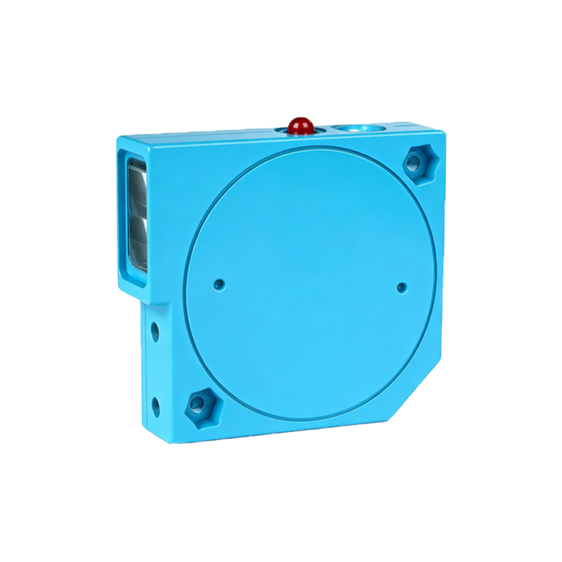
Reflective photoelectric sensors operate on a fundamental principle of optoelectronics. They integrate both a light emitter, typically an LED or laser diode, and a photodetector within a single housing. The emitter projects a beam of light towards a target surface. This light is then reflected, either diffusely or specularly, back towards the sensor. The integrated photodetector receives this reflected light and converts its intensity into an electrical signal. The presence, absence, or distance of the target is determined by analyzing the strength of this received signal. The entire process is governed and enabled by the application of a specific operating voltage, which powers the emitter circuit and the signal processing electronics. This voltage is the lifeblood of the sensor, dictating its performance, reliability, and compatibility with control systems.
The Critical Role of Operating Voltage in Sensor Performance
The operating voltage is not merely a power requirement; it is a defining parameter that influences several key aspects of sensor functionality. Primarily, it directly affects the intensity and stability of the emitted light beam. An under-voltage condition can lead to a dim, unstable light output, reducing the sensing range and making the sensor susceptible to ambient light interference. Conversely, an over-voltage condition, unless within specified tolerances, can overdrive the emitter, leading to premature aging, wavelength shift, or catastrophic failure. Furthermore, the operating voltage powers the internal amplifier and comparator circuits that process the photodetector's signal. A stable voltage supply ensures consistent switching thresholds, accurate analog output signals (in measuring sensors), and reliable noise immunity. Voltage fluctuations can cause erratic switching or drift in measurement values, compromising the integrity of the automated process.
Common Operating Voltage Standards and Ranges
Reflective photoelectric sensors are designed to integrate seamlessly into industrial control systems, which have standardized voltage levels. The most prevalent operating voltage for DC sensors is 10-30 VDC. This wide range allows compatibility with common 12VDC and 24VDC power supplies used in factories and machinery. Sensors with a 10-30 VDC rating offer flexibility and are resilient to minor voltage sags or surges. For longer-range or more demanding applications, some sensors may require a stricter range, such as 24VDC ±10%. AC-powered sensors are also available, typically operating at 90-250 VAC, allowing direct connection to mains power in certain regions or applications. It is paramount to consult the sensor's datasheet for its exact specified voltage range (e.g., "Operating voltage: 12-24 VDC" or "Supply voltage: 20-30 VDC") and never assume compatibility.
Connecting to Power: Sourcing (PNP) vs. Sinking (NPN) Configurations
The operating voltage is applied within one of two primary wiring configurations, defined by the type of output transistor: PNP (sourcing) or NPN (sinking). This choice is critical for interfacing with the controller (PLC). In a PNP sensor, the output switch connects the load to the positive supply voltage (+V). When active, it "sources" current to the load. In an NPN sensor, the output switch connects the load to the common negative (0V). When active, it "sinks" current from the load. The operating voltage for the sensor itself remains consistent (e.g., 24VDC), but the wiring to the load and PLC input changes. Selecting the wrong type for your PLC's input card will result in a non-functional circuit. Always verify the PLC input module's requirements before selecting a sensor output type.
Voltage Considerations for Specialized Sensor Types
Advanced reflective sensor types impose specific considerations on operating voltage. Background suppression sensors, which use triangulation to measure distance irrespective of color or reflectivity, often have more sensitive analog circuitry requiring a very clean and stable voltage supply to maintain accuracy. Contrast sensors, designed to detect minute differences in surface grayscale, similarly benefit from regulated power to ensure consistent emitter output and signal processing. For sensors with analog current outputs (4-20mA) or analog voltage outputs (0-10V), the operating voltage powers the output driver circuit. Fluctuations here can directly translate to errors in the transmitted signal. In harsh electrical environments, using a separate, regulated power supply or incorporating line filters is recommended to protect these sensitive devices from noise and transients.
Practical Guidelines for Voltage Supply and Protection
Ensuring a proper voltage supply is a cornerstone of reliable sensor installation. First, always use a power supply whose rated voltage falls within the sensor's specified range. For a 10-30 VDC sensor, a 24VDC supply is ideal. Second, consider the voltage drop over long cable runs; using a slightly higher gauge wire can mitigate this. Third, implement protective measures. Fusing the supply line is essential to protect against short circuits. In environments with inductive loads (relays, solenoids), use flyback diodes or transient voltage suppressors to clamp voltage spikes that could damage the sensor's electronics. Finally, for critical applications, monitor the supply voltage at the sensor's terminals during machine operation to confirm it remains within tolerance under all load conditions. A small investment in a stable, clean power source prevents costly downtime and ensures consistent sensor performance over its operational lifespan.