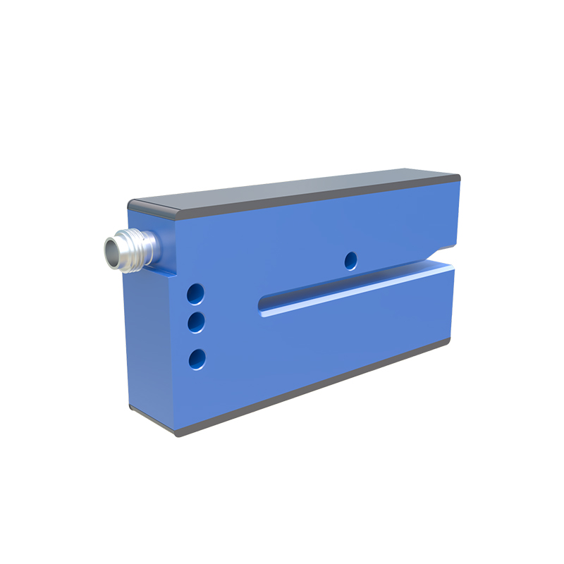
Introduction to Photoelectric Speed Sensing
A 32-photoelectric sensor, often referred to as an encoder with 32 pulses per revolution, is a cornerstone device in modern industrial automation for non-contact speed measurement. This sensor operates on the fundamental principle of photoelectricity, where a light source, typically an LED, and a photodetector are positioned on opposite sides of a rotating disk. This disk, attached to the shaft of the motor or rotating equipment, is marked with 32 precisely spaced slots or reflective segments. As the disk rotates, it intermittently interrupts or reflects the light beam, generating a series of electrical pulses. The frequency of these pulses is directly proportional to the rotational speed. The high resolution of 32 pulses per revolution provides a significant advantage, allowing for the detection of very fine speed variations and enabling precise control in applications ranging from conveyor belt monitoring to high-speed spindle drives. Its non-contact nature ensures minimal wear, long service life, and maintenance-free operation in harsh industrial environments filled with dust, vibration, and temperature fluctuations.
System Configuration and Installation Guidelines
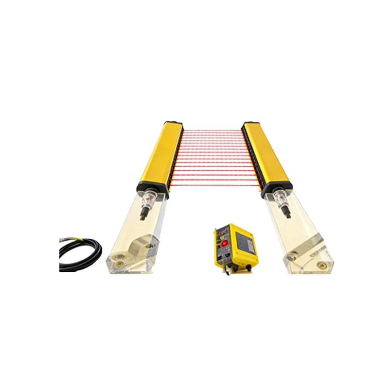
Proper installation is critical for achieving accurate and reliable speed data from a 32-photoelectric sensor system. The core components include the sensor head, the slotted or coded disk, a stable mounting bracket, and the signal processing unit or programmable logic controller (PLC). The sensor must be aligned with meticulous precision; the gap between the sensor's optical face and the rotating disk should be maintained within the manufacturer's specified range, usually a few millimeters. Misalignment can lead to weak or missed pulses, resulting in erroneous speed calculations. The disk must be securely mounted on the target shaft, ensuring minimal radial and axial runout to prevent signal jitter. Environmental factors must be considered: protective housings may be necessary for sensors exposed to heavy oil mist or coolant splash. Furthermore, electrical connections should be shielded to prevent electromagnetic interference (EMI) from nearby motors and variable frequency drives (VFDs), which can introduce noise into the pulse signal and corrupt measurement integrity.
Signal Processing and Speed Calculation Methodology
The raw output from the sensor is a train of square wave pulses. The primary method for speed calculation is the frequency measurement technique. A high-speed counter input on a PLC or a dedicated tachometer module captures the number of pulses (N) over a precisely timed gate period (T), often configurable from milliseconds to seconds depending on the required response time. The rotational speed in Revolutions Per Minute (RPM) is then calculated using the formula: RPM = (N / T) * (60 / PPR), where PPR is the pulses per revolution, which is 32 in this case. For instance, if 640 pulses are counted in a 0.5-second gate period, the speed is (640 / 0.5) * (60 / 32) = 2400 RPM. For even higher precision at low speeds, the period measurement method is employed, which measures the time between consecutive pulses. Advanced systems often use microprocessors to implement digital filtering algorithms, such as moving averages or Kalman filters, to smooth out signal noise and provide a stable, accurate speed reading for closed-loop control systems.Critical Applications in Industrial Automation
The 32-photoelectric sensor finds extensive use across diverse industrial sectors due to its reliability and precision. In packaging machinery, it monitors the speed of film feed rollers to ensure consistent material flow and prevent tearing. On assembly lines, it measures conveyor belt velocity for synchronizing robotic pick-and-place operations. In the textile industry, it controls the speed of spinning frames and looms. A vital application is in motor control and drive systems, where it provides essential feedback for Variable Frequency Drives (VFDs) to maintain constant torque or speed under varying loads. Furthermore, it is indispensable in safety systems, such as monitoring the overspeed or underspeed of critical fans, pumps, and escalators, triggering alarms or shutdowns to prevent equipment damage or hazardous situations. Its role in predictive maintenance is also growing, where trend analysis of speed fluctuations can indicate bearing wear or misalignment before catastrophic failure occurs.