Understanding the Core Components and Working Principle
Before beginning any adjustment procedure, a solid understanding of the sensor's components and operation is essential. A photoelectric distance sensor, often a type of diffuse or background suppression sensor, operates by emitting a beam of light (typically infrared, red, or laser) from an emitter. The light reflects off the target object, and a portion returns to the receiver. The sensor's internal electronics then calculate the distance based on the characteristics of the reflected light, such as the angle of return (triangulation principle for background suppression) or the time-of-flight for more precise laser models. Key components include the emitter lens, receiver lens, sensitivity adjustment potentiometer (often labeled SENS or similar), and a teach-in button or programming interface. Familiarity with the specific model's datasheet is non-negotiable for correct interpretation of indicator LEDs and adjustment points.
Pre-Adjustment Safety and Setup Checklist
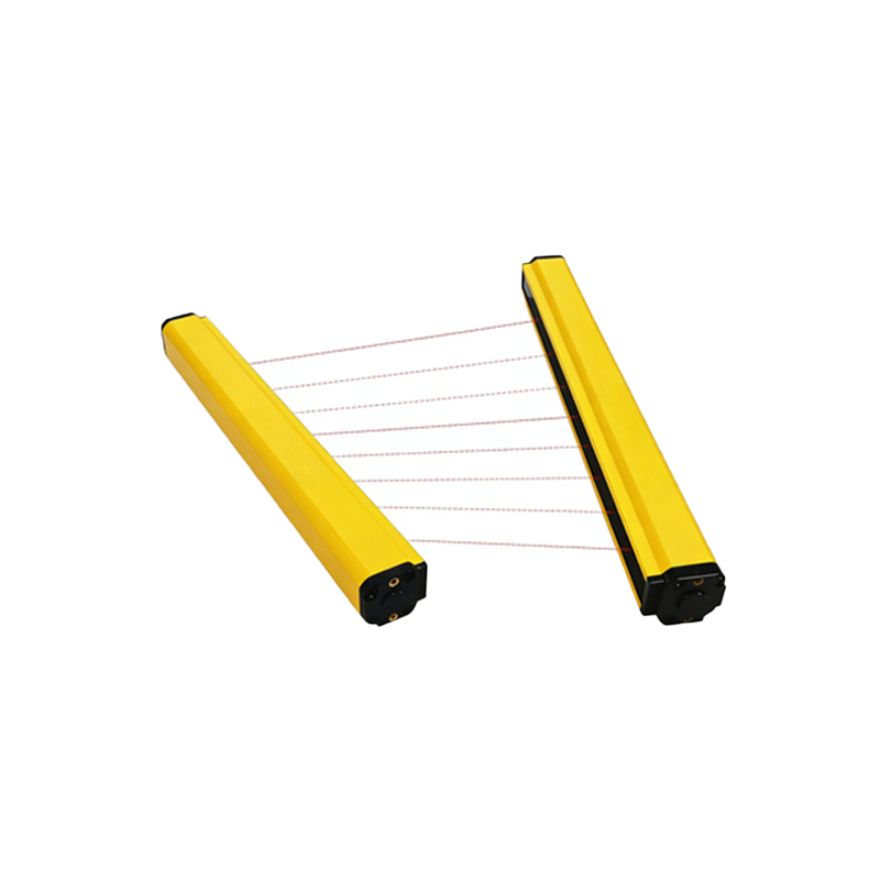
Safety and proper setup form the foundation of a successful calibration. First, ensure all power to the machine or system is locked out and tagged out (LOTO) according to standard safety protocols. Physically mount the sensor securely in its intended location, ensuring it is aligned correctly with the expected target path. Verify the electrical connections, matching the brown wire (typically +V), blue wire (0V or common), and black wire (output) to your power supply and controller inputs. Apply power. It is crucial to have the actual target object, or a perfect representative in terms of size, color, and surface finish, available for the adjustment process. Ambient light conditions should mirror the operational environment, as strong external light sources can interfere with performance.
Step-by-Step Sensitivity and Range Adjustment Procedure
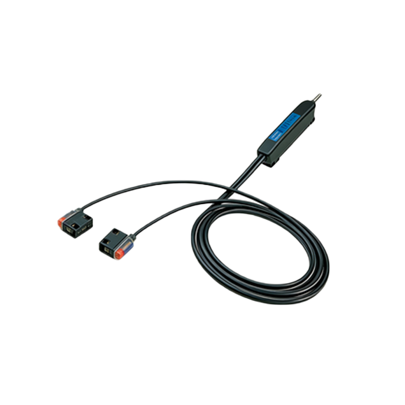
With the target object positioned at the desired sensing distance, the fine-tuning begins. Most sensors feature a multi-turn potentiometer for sensitivity adjustment. Turn the potentiometer slowly clockwise to increase sensitivity (increased sensing distance) or counter-clockwise to decrease it. Observe the sensor's output indicator LED. The goal is to set the sensitivity so that the output switches reliably when the target is present at the maximum required distance, and remains off when the target is absent. For sensors with a teach-in function, the process is more automated: position the target at the desired switch point, press and hold the teach button until the LED confirms (e.g., blinks twice), then remove the target and press the button again to set the background suppression point. Repeat this process 3-5 times to ensure consistency and repeatability.
Verifying Performance and Setting Hysteresis
After the initial setting, rigorous testing is mandatory. Move the target object towards and away from the sensor repeatedly, noting the exact points where the output switches on and off. The difference between these two points is the hysteresis, which prevents output chatter when a target is at the threshold. If the hysteresis is too small, the sensor may oscillate; if too large, it may not detect reliably. Adjust the sensitivity slightly to achieve an appropriate hysteresis band as specified in the datasheet, typically a few millimeters to a centimeter depending on the sensing range. Test with targets of varying reflectivity if applicable, and under different ambient light conditions to ensure robustness.
Troubleshooting Common Adjustment Issues
Several common issues can arise during adjustment. If the sensor cannot achieve the required sensing distance, check for insufficient target reflectivity, contamination on the lenses, or misalignment. Cleaning the lenses with a soft, lint-free cloth is often necessary. If the output is unstable or chatters, external optical interference from other light sources, reflective surfaces in the background, or electrical noise on the supply lines may be the cause. Increase hysteresis, use shielding, or employ sensors with modulated light to reject ambient light. For background suppression sensors failing to ignore a distant background, re-perform the teach-in procedure meticulously, ensuring the background is correctly "taught" as the non-target condition.
Best Practices for Long-Term Stability and Maintenance
Once optimally adjusted, document the settings, including the potentiometer position or teach-in reference. Implement a periodic maintenance schedule to inspect sensor alignment and lens cleanliness. Environmental factors such as temperature fluctuations, accumulation of dust, or mechanical vibration can cause drift over time. Consider using sensors with high IP ratings for harsh environments and those featuring automatic compensation for contamination or temperature. Regularly verify the sensor's performance as part of preventative maintenance to avoid unplanned downtime, re-checking the sensing distance and hysteresis against the original documented benchmarks.