Introduction to Photoelectric Sensing Technology
Photoelectric sensors are indispensable components in modern industrial automation, robotics, and smart systems. These devices operate on the principle of detecting changes in light intensity to sense the presence, absence, or distance of an object. They typically consist of a light emitter, often an LED or laser diode, and a photodetector, such as a phototransistor or photodiode. The core function involves the emitter projecting a light beam; when an object interrupts or reflects this beam, the detector registers a change in the received light, which is then converted into an electrical signal. This technology offers significant advantages, including non-contact operation, high speed, long sensing ranges, and reliability in harsh environments. Its applications span from simple object detection on conveyor belts to complex positioning tasks in precision machinery. Understanding this foundational technology is crucial for effectively integrating it with control systems like the ubiquitous 8051 microcontroller family.
Core Components and Working Modes
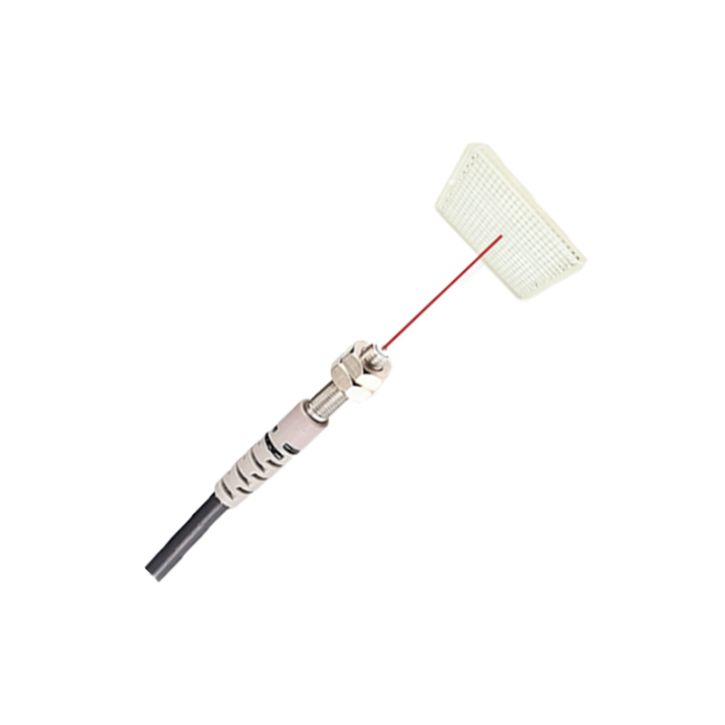
Photoelectric sensors are primarily categorized into three fundamental working modes: through-beam, retro-reflective, and diffuse reflective. In the through-beam mode, the emitter and receiver are separate units placed opposite each other. Detection occurs when an object physically breaks the light beam traveling from the emitter to the receiver. This mode offers the longest sensing distance and highest reliability. The retro-reflective mode positions both emitter and receiver in the same housing, utilizing a reflector to bounce the light beam back. An object is detected when it blocks this reflected beam. The diffuse reflective mode, also with a combined emitter and receiver, relies on the object itself to reflect light back to the detector. Each mode has distinct trade-offs in terms of range, target material dependency, and installation complexity, which must be carefully considered during system design.
The 8051 Microcontroller as an Integration Platform
The 8051 microcontroller architecture remains a cornerstone in embedded systems education and numerous industrial applications due to its simplicity, robustness, and extensive support ecosystem. For interfacing sensors, its key features include digital I/O ports, timers/counters, and interrupt capabilities. When connecting a photoelectric sensor, the digital output from the sensor's built-in amplifier/comparator circuit is typically routed to one of the 8051's input pins. The microcontroller can poll this pin's status or, for faster response, configure an external hardware interrupt to be triggered upon a state change from the sensor. The 8051's program memory holds the firmware that dictates the system's logic—such as activating a solenoid, incrementing a counter, or sending an alert—based on the sensor's input. Its ability to manage multiple sensors and peripherals makes it an ideal, cost-effective brain for automated control units.
Circuit Design and Hardware Interfacing
A reliable hardware interface is critical for noise immunity and signal integrity. Most industrial photoelectric sensors provide a digital output, often in a transistor-transistor logic (TTL) or open-collector configuration. For a standard TTL output, a direct connection to an 8051 port pin, possibly with a current-limiting resistor, may suffice. For open-collector outputs, a pull-up resistor to the Vcc is mandatory to ensure a defined high logic level. If the sensor operates at a different voltage level than the microcontroller, level-shifting circuits using optocouplers or voltage divider networks become necessary to protect the 8051's I/O pins. Power supply decoupling capacitors should be placed near both the sensor and microcontroller to filter electrical noise, a common issue in industrial settings. Proper grounding practices must be followed to avoid ground loops that could cause erratic sensor readings.
Software Implementation and Code Logic
The software firmware transforms raw sensor signals into actionable control commands. Initialization code configures the relevant 8051 port pins as inputs and may set up timers or interrupt vectors. For basic polling, the main program loop continuously reads the sensor pin. A more efficient method uses external interrupts. When the sensor's output changes state (e.g., from high to low indicating an object is detected), it triggers an interrupt service routine (ISR). This ISR executes immediately, allowing for precise timing-critical responses like capturing a timestamp or triggering an immediate output. Debouncing logic, either in hardware with a capacitor or in software by introducing a short delay after a state change, is often required to filter out mechanical vibrations or electrical glitches. The core application logic within the ISR or main loop then executes the desired control action.
Practical Application Example: Object Counter
Consider a practical application: an automated object counter on a production line. A through-beam photoelectric sensor is installed across a conveyor belt. Each object passing through breaks the beam. The sensor's output is connected to the INT0 pin of the 8051, configured for a falling-edge triggered interrupt. Inside the INT0 ISR, a software debounce delay of 10-50 milliseconds is implemented. After confirming a valid detection, a counter variable in RAM is incremented. The main program periodically updates this count on a connected LCD display and can compare it to a preset target value. Upon reaching the target, the 8051 can de-energize a motor control relay via another output pin, stopping the conveyor. This example showcases the seamless integration of sensing, processing, and control.
Troubleshooting and Optimization Techniques
System integration often encounters challenges. Common issues include false triggering due to ambient light interference, which can be mitigated by using modulated light sensors or installing physical shields. Inconsistent detection ranges may stem from power supply fluctuations or misalignment of optical components. Software techniques like implementing moving average filters on sensor readings can smooth out noise. For maximizing performance, consider using the 8051's power-saving modes when the system is idle, waking it via a sensor interrupt. Always verify the sensor's response time specifications against the 8051's instruction cycle time to ensure the microcontroller can keep pace with high-speed events. Thorough testing under real-world conditions is the final, essential step for validation.
Conclusion and Future Outlook
The combination of photoelectric sensors and the 8051 microcontroller creates a powerful, versatile platform for a vast array of automation tasks. This synergy leverages the sensor's precise physical-world detection with the microcontroller's flexible digital processing and control capabilities. While modern 32-bit microcontrollers offer more power, the 8051 continues to be a relevant and excellent choice for cost-sensitive, reliable, and well-understood applications. Future advancements may involve integrating smart sensors with digital communication protocols like IO-Link, which could interface with enhanced 8051 derivatives featuring UART or SPI peripherals. Mastering this fundamental integration provides engineers with a critical skill set applicable to more complex embedded systems, forming a solid foundation for innovation in industrial IoT and intelligent machine design.