Understanding Through-Beam Photoelectric Sensor Fundamentals
Through-beam photoelectric sensors, often called opposed-mode sensors, consist of two separate units: a transmitter and a receiver. The transmitter emits a continuous beam of light, typically infrared, visible red, or laser. The receiver, positioned directly opposite, detects this beam. An object is sensed when it interrupts the light path between the two units. This design provides the longest sensing range and highest excess gain of any photoelectric sensing mode, making it ideal for detecting small, opaque objects or for use in dirty environments. The key to their reliable operation lies in precise alignment and proper adjustment. Misalignment is the most common cause of failure, leading to false triggers or missed detections. Before any adjustment, ensure the sensor is correctly selected for the application, considering factors like required sensing distance, object size, environmental conditions (dust, moisture, ambient light), and the required response time.
Pre-Installation Planning and Mounting
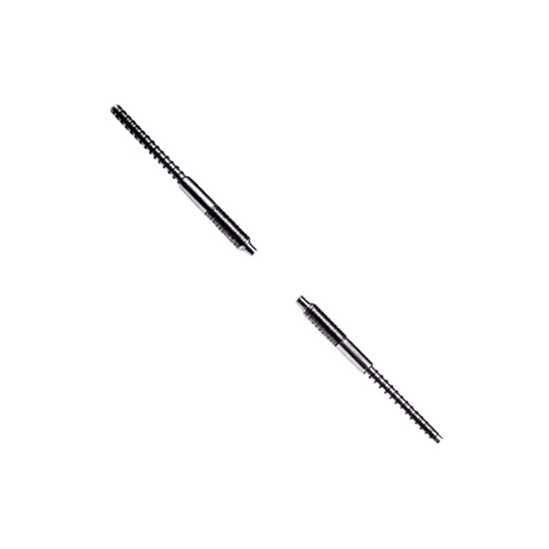
Successful adjustment begins with robust mechanical mounting. Use rigid brackets or mounting hardware to secure both the transmitter and receiver. Vibration or movement in the mounting surface can cause misalignment over time. Ensure the mounting surface is stable and the brackets are tightened securely. Position the units so that the light path is perpendicular to the direction of object travel for the most consistent beam break. Consider the height at which the object will pass; the beam should intersect the most reliable part of the object. Allow for adequate clearance around the beam path to prevent accidental interruption by fixtures, accumulated debris, or personnel. It is also critical to verify that the electrical connections are correct according to the sensor's datasheet, providing the proper voltage and ensuring the output load is within specifications.
The Initial Coarse Alignment Procedure
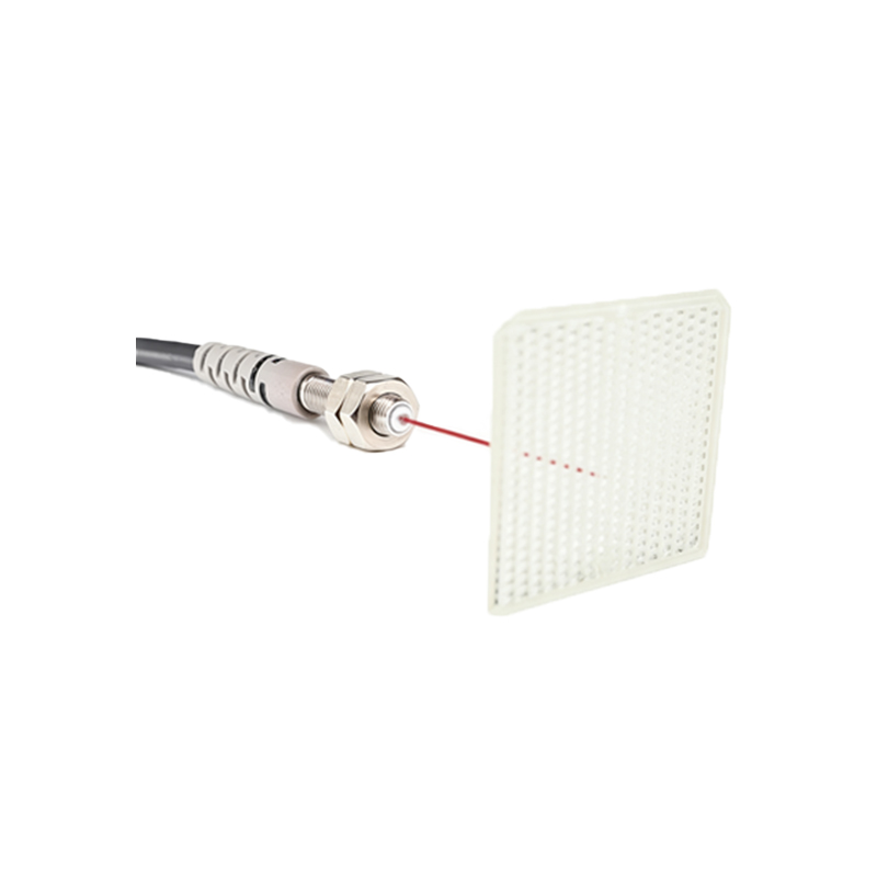
The first step in alignment is a coarse adjustment to get the beam approximately on target. Many through-beam sensors feature built-in visual aids. Transmitters often have a "beam on" indicator LED, and receivers may have a "power on" and "signal strength" indicator. Begin by powering both units. Manually point the transmitter in the general direction of the receiver. On the receiver, observe the signal strength indicator. This is typically a series of LEDs that light up as alignment improves, or a single LED that changes color from red (no beam) to green (beam received). Slowly adjust the horizontal and vertical angle of the transmitter until you achieve a stable, maximum signal indication on the receiver. Some high-precision models use a laser dot for visible alignment, which significantly simplifies this process.
Fine-Tuning for Maximum Signal Stability
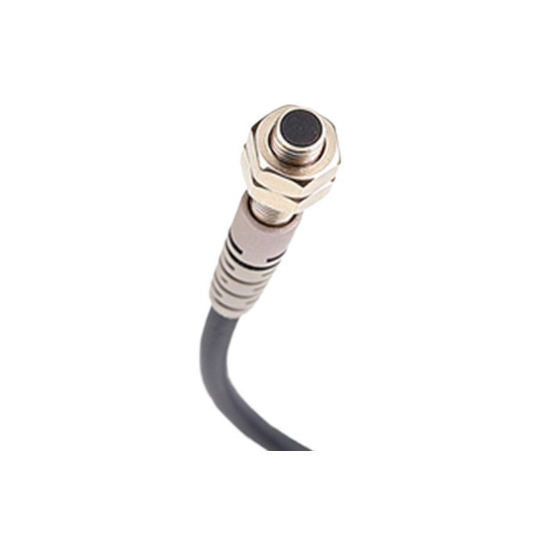
Once coarse alignment is achieved, fine-tuning is necessary for long-term reliability. Even with a strong signal, minor misalignments can make the system vulnerable to environmental disturbances. Use the receiver's alignment indicators meticulously. The goal is not just to get a "beam received" signal, but to achieve the highest possible signal strength reading. Carefully make minute adjustments to the transmitter's position, tracking the change on the receiver's indicator. Find the "sweet spot" where the indicator shows peak strength. For sensors with analog signal output or a bar-graph display, center the reading. After adjusting the transmitter, you may need to slightly adjust the receiver as well to ensure it is perfectly facing the incoming beam. Lock all adjustment screws firmly once the optimal position is found, but avoid over-tightening which might shift the housing.
Utilizing Alignment Tools and Advanced Features
For challenging installations over long distances or in hard-to-access locations, specialized tools are invaluable. A laser alignment tool can be used to project a visible beam from the transmitter for precise targeting. An optical sight, similar to a rifle scope, can be mounted on the sensor housing to visually aim at the opposite unit. For digital or "teach-in" sensors, utilize their advanced programming features. These sensors often allow you to set the operating point at the current signal strength during alignment. Some models feature automatic alignment functions or can store multiple alignment profiles for applications where sensors are moved periodically. Always consult the manufacturer's manual for model-specific alignment routines and feature explanations.
Environmental Compensation and Testing
After mechanical and electrical alignment, the system must be tested under real-world operating conditions. Environmental factors like airborne dust, steam, oil mist, or intense ambient light (sunlight, welding arcs) can scatter or overpower the sensor beam. Test the sensor by running the actual objects or a test piece through the beam repeatedly. Monitor for consistent detection. If false triggers occur, investigate potential sources of optical interference. Solutions may include using sensors with modulated light (which ignores steady ambient light), installing physical shrouds or tubes around the beam path, or switching to a different light wavelength (e.g., from red to infrared) less affected by the interference. Ensure that lens surfaces are kept clean, as buildup can attenuate the signal.
Troubleshooting Common Alignment Issues
Persistent problems often have identifiable causes. If the receiver cannot achieve a stable signal, double-check the power supply and wiring. Verify that the transmitter and receiver are a matched pair from the same manufacturer and product family, as operating frequencies and modulation codes must be compatible. If the signal is unstable (flickering indicator), it suggests marginal alignment or environmental interference. Re-perform the fine alignment procedure. For intermittent operation, inspect for mechanical looseness, vibration, or thermal expansion that might shift the units. Remember that the sensing range listed in catalogs is for ideal conditions; always derate for harsh environments. If all else fails, temporarily shorten the distance between units or use a sensor with higher excess gain to overcome alignment difficulties or dirty lenses.
Establishing a Preventive Maintenance Schedule
Alignment is not a one-time task. A preventive maintenance schedule is essential for continuous operation. Periodically inspect the sensor alignment and signal strength. Clean the lenses of both transmitter and receiver with a soft, lint-free cloth and appropriate cleaner to remove dust, oil, or condensation. Check the tightness of mounting hardware and brackets. Document the baseline signal strength reading after initial installation; a gradual decline in this reading during maintenance checks can indicate lens fouling or creeping misalignment, allowing for correction before a failure occurs. By integrating these adjustment and maintenance practices, through-beam photoelectric sensors deliver years of highly reliable, precise object detection in demanding industrial automation applications.